
Spray head structure of combined 3D printer

A technology of 3D printers and nozzles, applied in the direction of additive processing, etc., can solve problems such as poor product quality, poor sealing, and overflow of melted materials, and achieve the effects of avoiding environmental pollution, improving quality, and avoiding clogging

Inactive Publication Date: 2015-11-11
CHENGDU I MAKE SCI & TECH
View PDF6 Cites 1 Cited by
  • Summary
  • Abstract
  • Description
  • Claims
  • Application Information

AI Technical Summary

Problems solved by technology

[0003] At present, some large-scale 3D printers produce long-term wear and tear of the sealing ring when the filament enters, causing air to enter the nozzle, resulting in poor product quality.
In addition, due to poor sealing, the molten material in the nozzle will overflow the nozzle from the inlet of the silk material, resulting in waste

Method used


Image

  • Spray head structure of combined 3D printer
  • Spray head structure of combined 3D printer

Examples


Embodiment Construction

[0010] The present invention will be described in further detail below through specific implementation examples and in conjunction with the accompanying drawings.

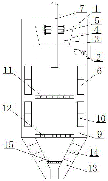
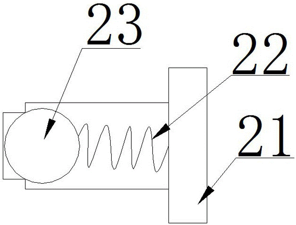
[0011] Figure 1-2 Shown is a nozzle structure of a combined 3D printer provided by the present invention, including: a feed housing 1, an electric heating wire heating ring 6, an exhaust device 2, an infrared heater 10, a sealing ring 3, a limit ring 4, Intermediate housing 9 , nozzle housing 13 , hot water heat conduction layer 14 , first filter screen 11 , second filter screen 12 , gas 23 , exhaust spring 22 , purifier 21 , third filter screen 15 and spring 5 . The feed end in the feed housing 1 is fixedly provided with a limit ring 4, the inner circular surface of the limit ring 4 is a conical surface, and the inner circular surface of the limit ring 4 is provided with a sealing ring 3 matched with the conical surface, A spring 5 is arranged between the sealing ring 3 and the inlet end face in the feed housing...


PUM


Abstract

The invention discloses a spray head structure of a combined 3D printer. The spray head structure comprises a spray head shell. The spray head shell comprises a feeding shell body, a middle shell body and a nozzle shell body. A limiting ring is fixedly arranged at the feeding end in the feeding shell body. The inner circular face of the limiting ring is a conical face and is provided with a sealing ring matched with the conical face of the limiting ring. A spring is arranged between the sealing ring and the inlet end face in the feeding shell body. A first filter net is arranged in the feeding shell body. An electric heating wire heating ring is arranged on the feeding shell body. A second filter net is arranged in the middle shell body. An infrared heater is arranged on the middle shell body. A third filter net is arranged in the nozzle shell body. A hot water heat conductive layer is arranged on the nozzle shell body. The sizes of filter holes in the first filter net, the second filter net and the third filter net are gradually reduced. By means of the spray head structure of the combined 3D printer, the product quality can be improved.

Description

technical field [0001] The invention relates to the technical field of 3D printers, in particular to a nozzle structure of a combined 3D printer. Background technique [0002] 3D printer, also known as three-dimensional printer, is a kind of cumulative manufacturing technology, that is, a machine of rapid prototyping technology. It is based on a digital model file, using special wax, powdered metal or plastic and other bondable materials. Print layers of adhesive material to create three-dimensional objects. At this stage 3D printers are used to manufacture products. The technology of constructing objects by printing layer by layer. The principle of a 3D printer is to put data and raw materials into the 3D printer, and the machine will build the product layer by layer according to the program. [0003] At present, some large-scale 3D printers produce long-term wear and tear of the sealing ring when the filament enters, causing air to enter the nozzle, resulting in poor pr...

Claims


Application Information

Patent Timeline
Patent Type & Authority Applications(China)
IPC IPC(8): B29C67/00B29C35/02B22F3/115B33Y30/00
Inventor 廖显洪雷赟肖葛洋
Owner CHENGDU I MAKE SCI & TECH
Learn More