
Door leaf vacuum thermal transfer printer

A technology of vacuum heat and transfer printing machine, applied in rotary printing machine, printing machine, transfer printing and other directions, can solve the problems of low transfer efficiency, poor authenticity of transfer pattern, increase in production cost, etc., to improve transfer efficiency , The transfer effect is good, and the effect of improving the transfer effect

Inactive Publication Date: 2015-11-11
CHONGQING HUAZHUODA POWER MACHINERY MFGCO LTD
View PDF0 Cites 3 Cited by
  • Summary
  • Abstract
  • Description
  • Claims
  • Application Information

AI Technical Summary

Problems solved by technology

[0002] In the prior art, transfer printing paper is used to transfer wood grain to the door leaf; the current technology only uses a single-layer silica gel plate on the top of the object, which has poor air permeability and cannot cling to the surface of the object. The authenticity of the transfer pattern is poor and the efficiency is low. The transfer carrier and the object to be transferred are difficult to separate, and the transfer requires professional personnel to operate, and the operation is complicated. At the same time, because only one side of the door leaf can be transferred, the transfer efficiency is low and the production cost is increased. Very bad for mass production

Method used


Image

  • Door leaf vacuum thermal transfer printer
  • Door leaf vacuum thermal transfer printer
  • Door leaf vacuum thermal transfer printer

Examples


Embodiment Construction

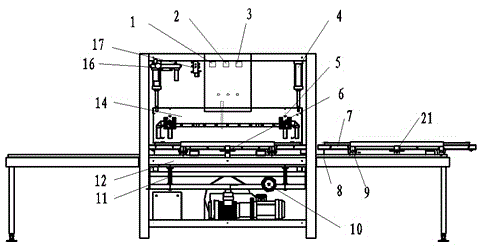
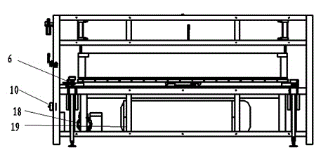
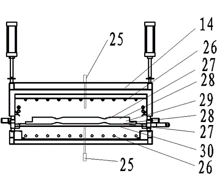
[0014] As an embodiment of the present invention, such as figure 1 , 2 As shown in , 3, a door leaf vacuum heat transfer machine, including a body frame, is characterized in that: a cylinder 4 is arranged on the upper end of the body frame, the cylinder is connected to the air source processor 16, and the lower end of the cylinder push rod is fixedly connected There is an upper heating chamber 14, and a lower heating chamber 12 is fixedly installed on the lower side of the body frame. A slide rail 8 is arranged between them, and the slide rail passes through the frame of the body. The slide rail is divided into three sections, left, middle, and right. There is a sealed chamber 7, the bottom of the sealed chamber is provided with a pulley 9 matching with the slide rail 8, a trigger block 21 is arranged on the side of the sealed chamber to cooperate with the travel switch 6 arranged on the body frame, and a vacuum valve is arranged at the bottom of the body frame. The vacuum ...


PUM


Abstract

The invention discloses a door leaf vacuum thermal transfer printer. The door leaf vacuum thermal transfer printer comprises a machine frame. An upper heating bin and a lower heating bin are arranged at the upper end and the lower end of the machine frame. The upper heating bin can move up and down. A sliding rail is arranged between the upper heating bin and the lower heating bin. The sliding rail penetrates the machine frame. The sliding rail is divided into a left section of sliding rail, a middle section of sliding rail and a right section of sliding rail. Lifting mechanisms are arranged at the positions, right opposite to the heating bins, of the middle section of sliding rail. The left section of sliding rail and the right section of sliding rail are provided with sealing bins. Sliding wheels matched with the sliding rail are arranged at the bottoms of the sealing bins. Trigger blocks are arranged on the side faces of the sealing bins and matched with a travel switch arranged on the machine frame. A vacuum pump connected with a vacuum buffering tank is arranged at the bottom of the machine frame. The sealing bins are communicated with the vacuum buffering tank through vacuum pipes. A vacuum controller is arranged between the vacuum buffering tank and the vacuum pipes. The machine frame is further provided with a time relay, and a gas source processor and the time relay are connected. The travel switch is connected with electromagnetic valves in a control system. The door leaf vacuum thermal transfer printer has the beneficial effects of being simple in structure, flexible in operation and good in transfer printing effect.

Description

Technical field [0001] The invention is a type of door transfer device. Specifically, it involves a type of door fan vacuum heat transferor. Background technique [0002] The existing technologies use transfer paper to the door fan for wood grain transfer technology; now the technology only uses a single -layer silicone sheet on the object, poor breathability, not to be attached to the surface of the object, the authenticity of the transfer pattern is poor, and the efficiency is low.The transfer carrier is difficult to peel off with the transfer objects, and professional personnel operations are required when transferring. At the same time, the operation of the door fan can only be transferred, which leads to the problem of low transfer efficiency and increased production cost.It is not conducive to mass production. Invention content [0003] In view of the above problems, the invention provides a type of door fan vacuum heat transferor, which has the characteristics of simple s...

Claims


Application Information

Patent Timeline
IPC IPC(8): B41F16/00
Inventor 郭正华段红文杨俊黄波张文政胡雷波
Owner CHONGQING HUAZHUODA POWER MACHINERY MFGCO LTD
Learn More