Four-connecting-rod mechanism for trolley pole

A technology of four-bar linkage mechanism and collector rod, which is applied in current collectors, power collectors, electric vehicles, etc., can solve problems such as off-line, pantograph collision, and safety accidents, so as to improve maintenance efficiency and reduce Work load, effect of reducing labor intensity

Active Publication Date: 2015-11-11
SUZHOU KAIBO YIKONG DRIVE TECH CO LTD
View PDF7 Cites 4 Cited by
  • Summary
  • Abstract
  • Description
  • Claims
  • Application Information

AI Technical Summary

Problems solved by technology

[0003] The patent application No. 03142211.X discloses a double-wire receiving type trolley bus pantograph, which is formed between the underframe, the lower arm, the pull rod, the upper arm, the balance bar, and the cross bar of the bow seat. Two double-connected planar four-bar linkage mechanisms, which mainly rely on the bow-raising cylinder to push the lower arm to swing, can support the horizontal bar of the bow head seat and the bow-top conductive slider to lift up and down, and the bow-top conductive slider of the pantograph to rise Finally, under the pulling force of the lifting bow spring, it keeps rising and keeps it in close contact with the wires of the catenary. The disadvantages are: (1) The speed of the pantograph is uniform during the lifting process. On the other hand, the pantograph cannot be lowered to a safe area in a short time after it is off-line, and the pantograph is likely to collide with objects around the vehicle, resulting in safety accidents; (2) when the vehicle is driving in the When the road is bumpy, it is easy to get off the line

Method used


Image

  • Four-connecting-rod mechanism for trolley pole
  • Four-connecting-rod mechanism for trolley pole
  • Four-connecting-rod mechanism for trolley pole

Examples


Embodiment 1

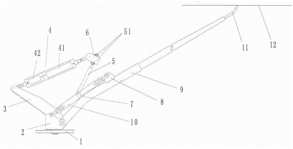
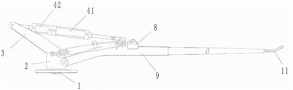
[0028] A four-bar linkage mechanism for collector rods, such as figure 1 As shown, including a bottom plate 1, a through hole (not shown) is opened on the bottom plate 1, and the bottom end of the support seat 2 extends into the through hole (not shown), and the support seat 2 and the The bottom plate 1 is axially connected, and a rotary cylinder (not shown) is installed on the support seat 2, and the support seat 2 can be pushed to rotate relative to the bottom plate 1 by the rotary cylinder (not shown in the figure). .

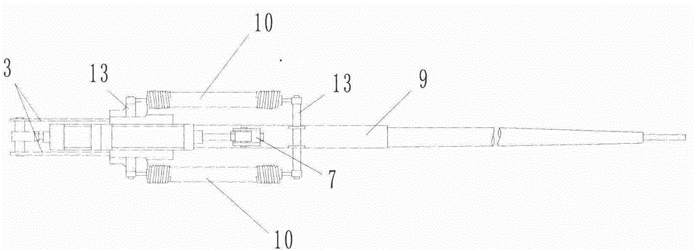
[0029] A boom 9 is connected with a pin shaft on the support base 2, and the boom 9 can rotate integrally with the support base 2; 8 and the support base 2 are respectively pierced with support rods 13, please combine figure 2 , different support rods 13 are in a parallel state, and springs 10 are fixed between the support rods 13, and the springs 10 are distributed on both sides of the boom 9. When the boom 9 is in a horizontal state, the springs 10 is ...

Embodiment 2

[0040] The rest are the same as in Embodiment 1, except that the third connecting rod 5 is a screw rod, and the top end of the third connecting rod 5 is connected to the connecting rod seat 6 through a nut 51. When the vehicle is at different heights, When driving on the catenary road, the driver can adjust the length of the screw mandrel flexibly by manually adjusting the nut 51, so that the boom 9 can be kept in the catenary state at different catenary heights, and the catenary can be lifted. Web flexibility.


PUM


Abstract

The invention discloses a four-connecting-rod mechanism for a trolley pole, and relates to the technical field of trolley buses. The four-connecting-rod mechanism comprises a base plate and a supporting base connected with the base plate. A large arm and a first connecting rod are connected to the supporting base. The first connecting rod is connected with a second connecting rod. A third connecting rod is connected between the second connecting rod and the large arm. A spring is connected between the large arm and the supporting base. Due to the fact that force applied by the spring on the large arm can be controlled by adjusting the lengths of the second and third connecting rods, the large arm can ascend and descend at different speeds to carry out active net touch and active net disengagement work, and meanwhile a trolley bus can be effectively prevented from being disengaged from a net in the driving process.

Description

technical field [0001] The invention relates to the technical field of trolleybuses, in particular to a mechanism for controlling collector poles to perform stable wiring and efficient lifting. Background technique [0002] Trolley bus is a kind of road public transportation that is usually powered by overhead catenary, driven by motor, and does not rely on fixed rails. Compared with ordinary passenger cars, trolley bus needs to install a pair of collector poles (also known as pantographs) on the roof. , used to receive electricity from the contact wire of the catenary and form a current path. Generally, the trolley bus is equipped with a power battery. In the section without the catenary, the power battery is powered by the collector pole after it is disconnected from the grid; in the section with the catenary, The collector pole supplies power to the trolley bus through the catenary, and charges the power battery at the same time. [0003] The patent application No. 03142...

Claims


Application Information

Patent Timeline
Patent Type & Authority Applications(China)
IPC IPC(8): B60L5/30
Inventor 郝韵
Owner SUZHOU KAIBO YIKONG DRIVE TECH CO LTD
Why Eureka
Try Eureka