WDM optical transimission system and optical amplifying apparatus

a transceiving system and optical amplifier technology, applied in the field of wdm optical transceiving system and optical amplifier, can solve the problems of signal level variation, transmission path fiber loss, transmission path loss change, etc., to improve signal reception sensitivity, and reduce the control speed of the effect of performance cycl

Inactive Publication Date: 2008-04-03
FUJITSU LTD
View PDF16 Cites 19 Cited by
  • Summary
  • Abstract
  • Description
  • Claims
  • Application Information

AI Technical Summary

Benefits of technology

[0022]According to the WDM optical transmission system of the present invention as described in the above, since a setting error of the gain, which occurs due to the measurement error of the span loss, is compensated by the correction value computed using the wavelength numbers information, even if the span loss in the optical transmission path or the number of wavelengths of the WDM signal light is varied, the optical amplifiers positioned on the upstream and downstream sides of the system can be controlled at high-speeds and with high precision. Therefore, it becomes possible to improve the signal reception sensitivity in the WDM optical transmission system. Further, although the correction using the wavelength numbers information is performed in the system, a control speed (performance cycles) thereof can be made lower as described in the above. In a conventional automatic level control using the wavelength numbers information, in order to suppress the level variation at the time when the span loss is varied at a high-speed, it is necessary to increase a control speed thereof as much as possible, and therefore, the level variation occurs due to a relation to a detecting time of the number of wavelengths. However, in the case where the wavelength numbers information is applied for correcting an error in an automatic level control by the span loss monitoring, the level variation as in the conventional control can also be resolved.

Problems solved by technology

However, in the above automatic gain control, there is a problem in that an output signal level of the optical amplifier is varied due to a change in the transmission path loss.
Further, there is also a possibility that stress, such as bending or the like, is subjected to the transmission path fiber for some reason, and therefore, the transmission path fiber loss is changed.
Further, in the above automatic level control, there is a problem in that the signal level variation occurs since it requires substantial time to obtain the wavelength numbers information on the WDM signal light.
However, in the detection of the number of wavelengths, due to constraints and the like on a detecting device, there may be the problematic case where the speeding-up of detecting time is difficult.
Consequently, in practice, it is difficult to approach ΔP to 0, and accordingly, the detecting device is designed such that the level variation of certain degree is allowed at the variation time of the number of wavelengths.
However, in the optical amplifier to which the automatic level control by the span loss monitoring as described above is applied, there is a problem in that a measurement error of the span loss is directly linked to a setting error of the signal output level.
Further, as shown in FIG. 8 for example, in the case where optical amplifying units 201 to 203 to each of which the automatic level control by the span loss monitoring is applied, are connected in multi-stages via transmission path fibers 211 to 213, there is a problem in that a measurement error of the span loss in each optical amplifying unit is accumulated.

Method used


Image

  • WDM optical transimission system and optical amplifying apparatus
  • WDM optical transimission system and optical amplifying apparatus
  • WDM optical transimission system and optical amplifying apparatus

Examples


first embodiment

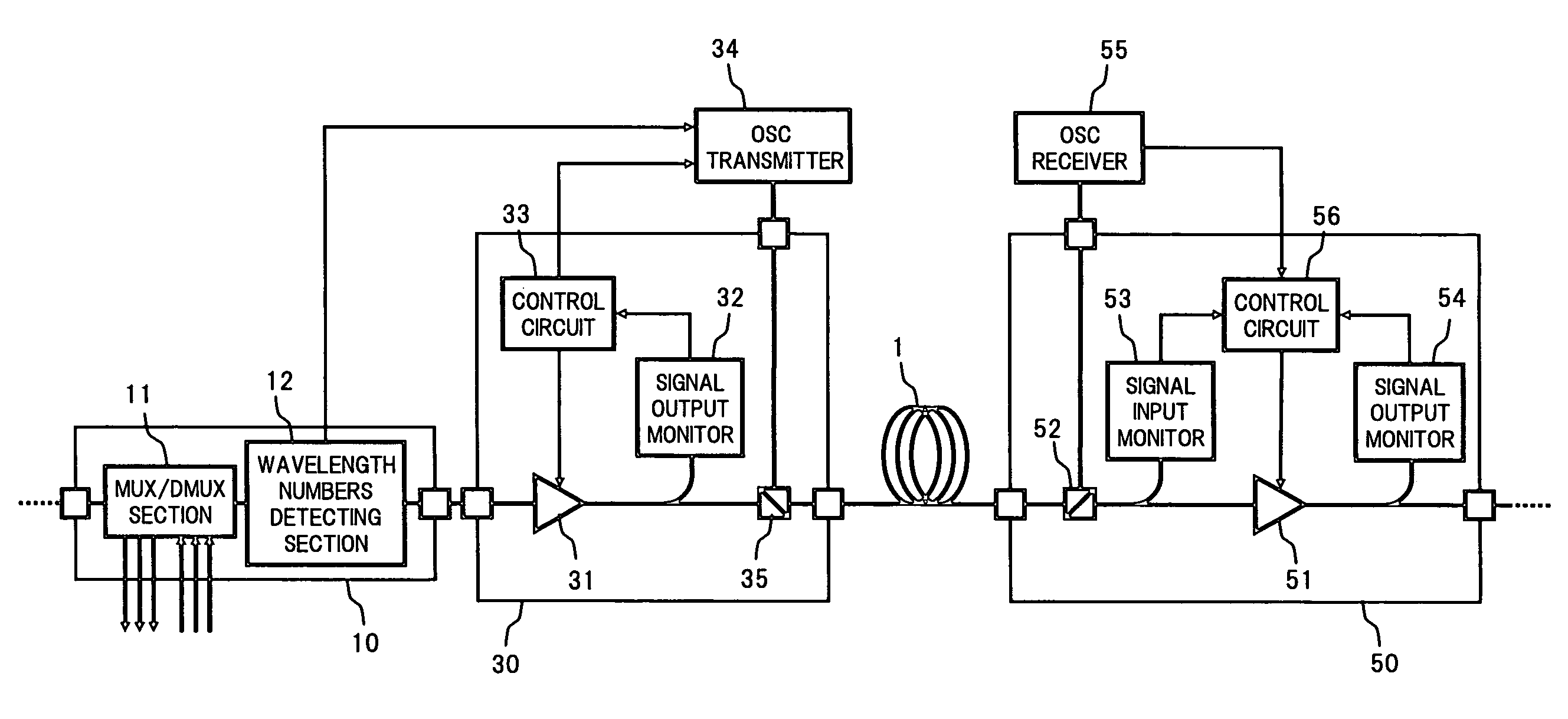
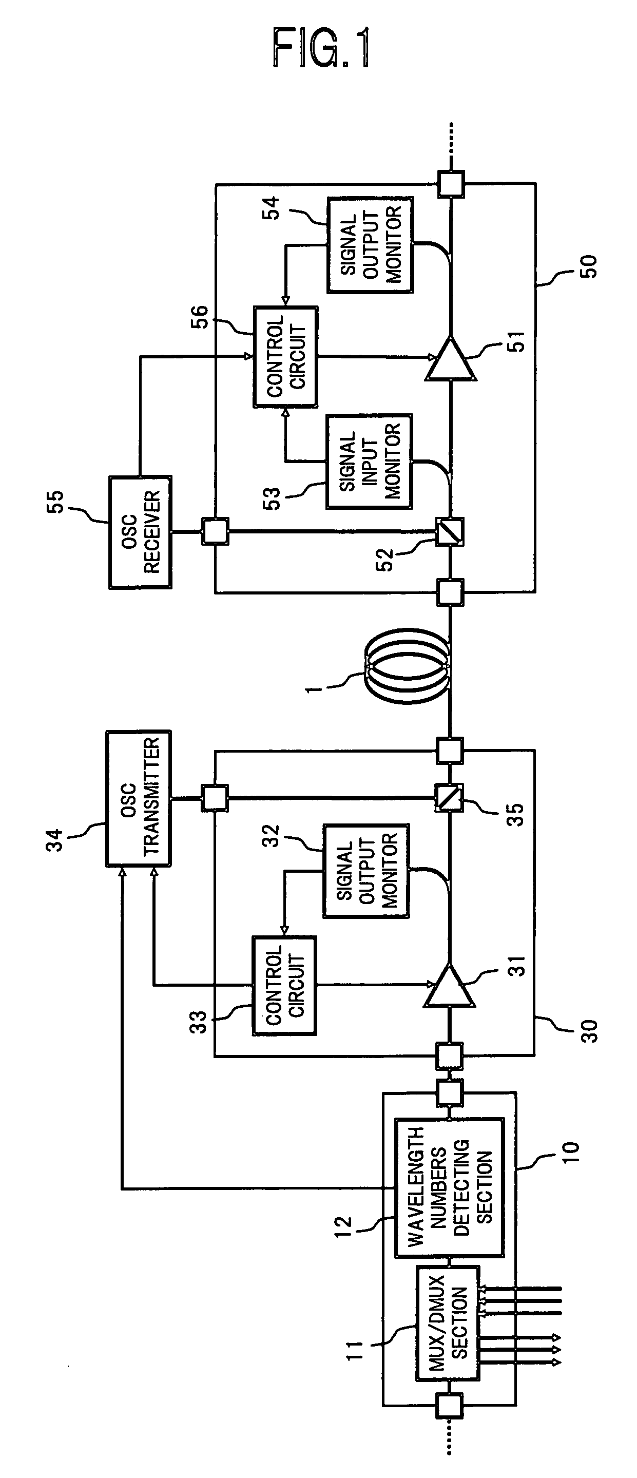
[0033]FIG. 1 is a block diagram showing a configuration of an essential part of a WDM optical transmission system using optical amplifiers according to the present invention.

[0034]In FIG. 1, the WDM optical transmission system in the present embodiment comprises, for example: an optical multiplexing / demultiplexing unit 10 which multiplexes / demultiplexes optical signals of desired wavelengths in a WDM signal light to be transmitted over a transmission path fiber 1 serving as an optical transmission path; an optical amplifying unit 30 connected to an output end of the optical multiplexing / demultiplexing unit 10; and an optical amplifying unit 50 to which the WDM signal light output from the optical amplifying unit 30 is input via the transmission path fiber 1. Herein, the optical multiplexing / demultiplexing unit 10 and the optical amplifying unit 30 constitute a part of an optical add-drop multiplexer (OADM) node on the WDM optical transmission system, and the optical amplifying unit ...

second embodiment

[0054]Next, there will be described the present invention.

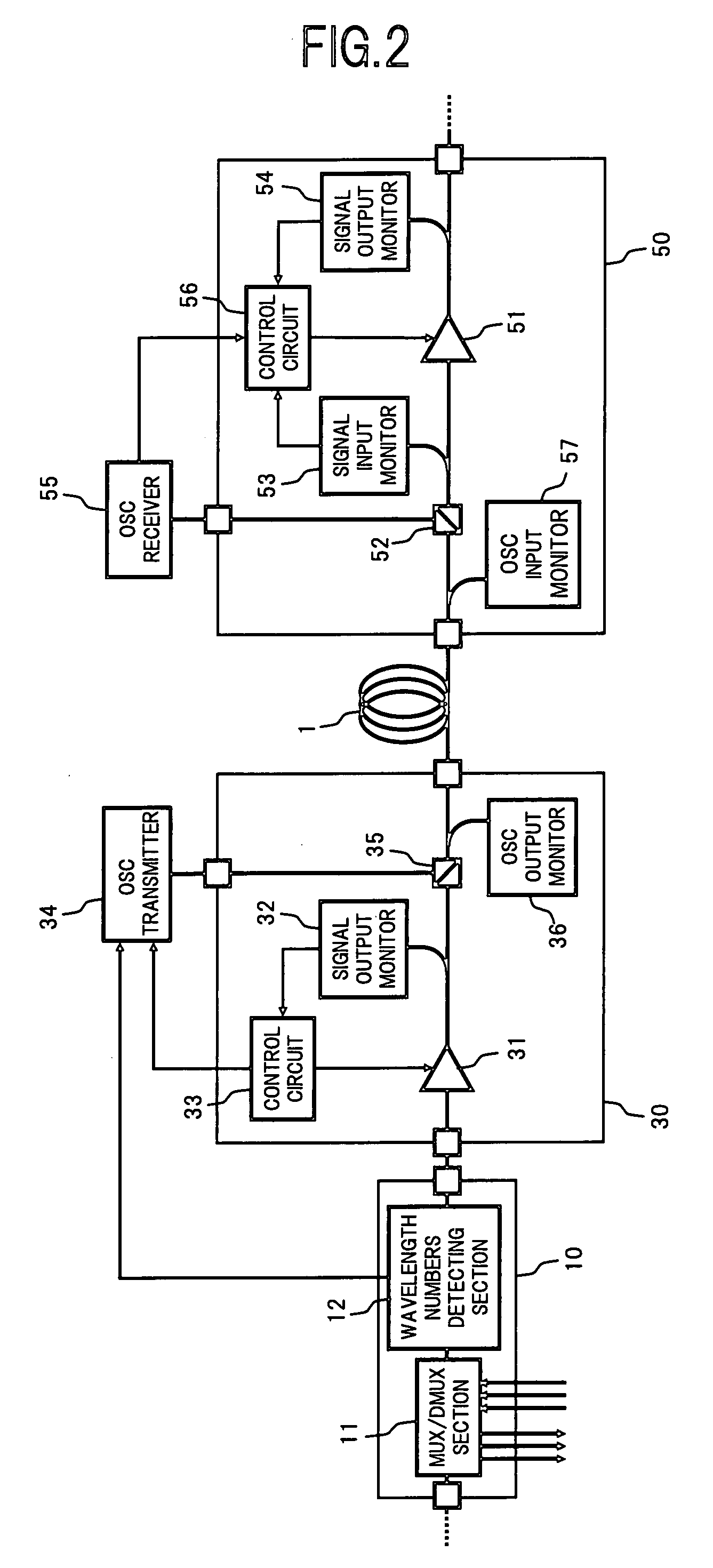
[0055]In the system configuration of the first embodiment shown in FIG. 1, in the case where the number of wavelengths of the WDM signal light which is sent from the upstream side optical amplifying unit 30 to the downstream side optical amplifying unit 50 becomes 0 wave, resulting in the wavelength discontinuity, it becomes difficult to monitor the span loss in the transmission path fiber 1. The reason of this is such that, as shown in the above formula (1), although the span loss SL is calculated using the total output power POUT(T) of the upstream side optical amplifying unit 30, which is obtained based on the signal output level information from the OSC receiver 55, and the total input power PIN(R) of the downstream side optical amplifying unit 50, which is obtained based on the signal input level information from the signal input monitor 53, if there occurs the wavelength discontinuity wavelengths in the WDM signal light...


PUM


Abstract

According to a WDM optical transmission system of the present invention, wavelength numbers information of a WDM signal light output from an upstream side optical amplifying unit to a transmission path fiber, and signal output level information thereof are transmitted to a downstream side optical amplifying unit utilizing a supervisory control light. In the downstream side optical amplifying unit, a loss (span loss) in the transmission path fiber is computed using the upstream side signal output level information and downstream side signal input level information, so that a gain to be set for a downstream side optical amplifier is calculated based on the computed loss, and also, the gain is corrected based on a difference between a target value of the signal output level computed using the wavelength numbers information and an actual measurement value thereof, so that the optical amplifier is controlled in accordance with the post-corrected gain. As a result, it becomes possible to reduce an influence by a measurement error of the span loss, to thereby control the optical amplifier at a high-speed and with high precision.

Description

BACKGROUND OF THE INVENTION[0001]1. Field of the Invention[0002]The present invention relates to a WDM optical transmission system which transmits a wavelength division multiplexed (WDM) light while amplifying it, and an optical amplifying apparatus, and in particular, to a WDM optical transmission system and an optical amplifying apparatus, in which the optical amplification is controlled so that a signal output level is held constant.[0003]2. Description of the Related Art[0004]In the case where an optical amplifier is used in a WDM optical transmission system, as methods of controlling an optical amplification operation of the optical amplifier, there have been known an automatic gain control (AGC) and an automatic level control (ALC). The automatic gain control is a method of setting a gain according to a transmission path loss at the time of device setting-up, and thereafter, continuing to hold the set gain. Further, the automatic level control is a method of setting a gain acc...

Claims


Application Information

Patent Timeline
Patent Type & Authority Applications(United States)
IPC IPC(8): H04J14/02H04B10/29H04B10/07H04B10/296H04J14/00
CPCH04J14/0221
Inventor ITOH, HIROYUKIKOMAKI, KOSUKE
Owner FUJITSU LTD
Why Eureka
Try Eureka