Flowing water-cooled sealing structure of bottomless muffle tank for well type carburizing furnace

A water-cooled sealing and carburizing furnace technology, applied in the field of workpiece heat treatment furnace sealing structure, can solve the problems of defective workpiece, unreachable cooling effect, leakage of sealing oil, etc., achieve excellent sealing effect, prevent spontaneous combustion, and improve safety Effect

Active Publication Date: 2018-01-05
CHONGQING AODIAN IND FURNACE
View PDF6 Cites 0 Cited by
  • Summary
  • Abstract
  • Description
  • Claims
  • Application Information

AI Technical Summary

Problems solved by technology

In the carburizing furnace with sealed oil tank in the prior art, the technology of the sealed oil tank has problems such as low safety and reliability. First, the sealing oil has the risk of burning under high temperature working conditions (it often occurs in China), especially the longer the heat treatment time , the temperature of the oil rises, and it is easier to spontaneously ignite; secondly, due to factors such as cooling effect and oil level, the cooling effect of itself cannot reach the best state, and the sealing oil may be blown away by the furnace gas to cause leakage when the furnace pressure is too high ;Once the sealing oil is blown away by the furnace gas to form a leak, the pressure in the carburizing furnace will drop rapidly, which cannot meet the process requirements at all, and the workpieces in the furnace will become defective and waste products to a large extent.

Method used


Image

  • Flowing water-cooled sealing structure of bottomless muffle tank for well type carburizing furnace

Examples


Embodiment Construction

[0013] The present invention will be described in further detail below in conjunction with the accompanying drawings.

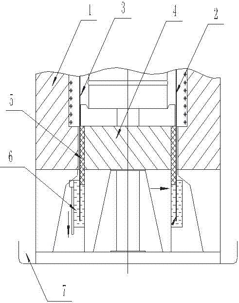
[0014] see figure 1 , the flowing water-cooled sealing structure of the bottomless muffle tank of the well type carburizing furnace of the present invention includes a carburizing furnace body 1, an inverted bottomless muffle tank 2 is arranged in the carburizing furnace body 1, and the carburizing furnace body The cavity in the middle of 1 forms a hearth 3, and the upper end of the bottomless muffle tank 2 is arranged in the hearth 3, and the open end passes downward through the hearth 4 at the bottom of the hearth 3, and passes through the hearth 4, and extends downward for a certain length; The heat-treated workpiece is installed in the muffle tank 2 and supported on the hearth 4, or supported on the material receiving base on the hearth 4; the improvement of the present invention is between the muffle tank 2 and the hearth 4, that is, on the muffle The t...


PUM


Abstract

The invention relates to a flow water-cooling sealing structure of a well type carburizing furnace bottomless muffle tank. The flow water-cooling sealing structure of the well type carburizing furnace bottomless muffle tank comprises a carburizing furnace body. The inverted bottomless muffle tank is arranged in the carburizing furnace body. An annular structure sealing layer is arranged between the muffle tank and a furnace platform, namely an inner cavity of the part, penetrating through the furnace platform, of the muffle tank. The gap between the muffle tank and the furnace platform is sealed by the structure sealing layer. A water cooling sealing groove is formed below the structure sealing layer, and cooling water is input into the water cooling sealing groove to cool the tail end of the muffle tank or cool the tail end of the muffle tank and the lower end of the structure sealing layer. The water-cooling sealing structure has the high safety, will not cause spontaneous combustion, avoids or even completely eradicates the spontaneous combustion phenomenon caused by traditional oil liquid sealing, and greatly improves safety. The gap is sealed by the structure sealing layer, the excellent sealing effect is achieved, the phenomenon that losing of the temperature and furnace pressure of the muffle tank or water flowing are caused through the gap is effectively prevented, the reliability is greatly improved, and inferior-quality products or waste products are prevented from being formed in the furnace body.

Description

technical field [0001] The invention relates to the technical field of a sealing structure of a workpiece heat treatment furnace, in particular to a flowing water-cooling sealing structure of a bottomless muffle for a well-type carburizing furnace. Background technique [0002] The sealing of the bottomless muffle tank of the original large-scale controllable atmosphere well-type carburizing furnace is all oil-sealed groove structure at the bottom of the furnace. It is rare (almost never seen) that other sealing technologies can be reliably applied in practice. Such as the disclosed name of CN2609939 is "well type gas carburizing furnace", and the application is a utility model patent of 03233981. The bottom muffle tank is placed in the sealed oil tank. In the carburizing furnace with sealed oil tank in the prior art, the technology of the sealed oil tank has problems such as low safety and reliability. First, the sealing oil has the risk of burning under high temperature w...

Claims


Application Information

Patent Timeline
Patent Type & Authority Patents(China)
IPC IPC(8): C23C8/20C23C8/44C23C8/64
Inventor 冯中堂
Owner CHONGQING AODIAN IND FURNACE
Why Eureka
Try Eureka