
Spinning channel system

A technology of spinning tunnels and tunnels, which is applied in dry spinning, textiles and papermaking, and complete sets of equipment for the production of artificial threads, etc. It can solve problems such as unreasonable distribution of spinning tunnel structures, unstable spinning quality, and elevated hot air temperature. , to achieve the effect of increasing solvent volatilization rate, reducing the mutual influence of filaments, and improving heat exchange efficiency

Inactive Publication Date: 2015-11-11
ZHEJIANG BAOLIAN FIBER SCI & TECH CO LTD
View PDF8 Cites 4 Cited by
  • Summary
  • Abstract
  • Description
  • Claims
  • Application Information

AI Technical Summary

Problems solved by technology

[0005] The structure distribution of the traditional spinning tunnel is unreasonable, the temperature rise of the hot air is limited, the heating is uneven, and the spinning quality is unstable

Method used


Image

  • Spinning channel system
  • Spinning channel system
  • Spinning channel system

Examples


Embodiment Construction

[0034] The present invention will be described in further detail below in conjunction with the accompanying drawings.

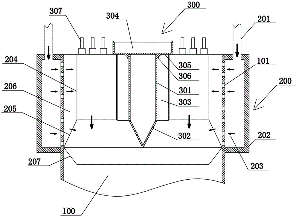
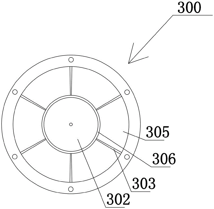
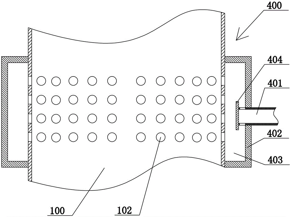
[0035] A spinning tunnel system, comprising a cylindrical tunnel body 100, an upper air inlet mechanism 200, a positive flow mechanism 300, a main return air mechanism 400, a secondary return air mechanism 500, a bottom return air mechanism 600, a spinning hot air circulation mechanism 700 and a spinning Silk hot air exhaust mechanism 800.

[0036] The upper air inlet mechanism 200 and the positive flow mechanism 300 are arranged on the top of the cylindrical shaft body 100 , and the upper air inlet mechanism 200 is arranged on the periphery of the positive flow mechanism 300 . The main air return mechanism 400 is fixedly arranged in the middle of the cylindrical shaft body 100 and between the upper air inlet mechanism 200 and the secondary air return mechanism 500 . The secondary air return mechanism 500 is disposed at the lower part of the cylindrical shaf...


PUM


Abstract

The invention belongs to the technical field of spinning devices, and relates to a spinning channel system. The spinning channel system comprises a cylindrical channel body, an upper air feed mechanism, a flow correcting mechanism, a main air return mechanism, an auxiliary air return mechanism and a bottom air return mechanism. The upper air feed mechanism and the flow correcting mechanism are arranged at the top of the cylindrical channel body, and the upper air feed mechanism is arranged on the periphery of the flow correcting mechanism; the main air return mechanism is fixedly arranged in the middle of the cylindrical channel body and located between the upper air feed mechanism and the auxiliary air return mechanism; the auxiliary air return mechanism is arranged on the lower portion of the cylindrical channel body and located above the bottom air return mechanism; the bottom air return mechanism is arranged at the bottom of the cylindrical channel body. While increasing the air volume of the channel, the spinning channel system ensures stability of airflow, so that the character of final spandex fiber finished products tends to be stable, and product differentiation is reduced.

Description

technical field [0001] The invention belongs to the technical field of spinning devices, and in particular relates to a spinning tunnel system. Background technique [0002] Spandex, also known as polyurethane fiber, is a kind of high elastic fiber, which has been widely used in various elastic fabrics, such as sportswear, daily clothing and other elastic thin fabrics, etc. It is an indispensable special fiber for the development of high-grade elastic textiles . [0003] Spandex has to go through many processes in the production process, and the last process is called spandex spinning. Dry spinning is a spandex spinning method with a wide range of applications. The process is as follows: the stock solution composed of spandex, DMAC and other additives is filtered in the spinning assembly, distributed to the spinneret and sprayed out from the spinneret. The raw liquid sprayed from the spinneret is evaporated by the high-temperature hot air up to 300°C in the spinning shaft ...

Claims


Application Information

Patent Timeline
Patent Type & Authority Applications(China)
IPC IPC(8): D01D13/02D01D5/04
Inventor 陈国梁沈伟松
Owner ZHEJIANG BAOLIAN FIBER SCI & TECH CO LTD
Learn More