

Rear-mounted slipform paver pavement slipform mold
A sliding-form paver, rear-mounted technology, applied in the direction of roads, roads, road repair, etc., can solve problems such as use restrictions
- Summary
- Abstract
- Description
- Claims
- Application Information
AI Technical Summary
Problems solved by technology
Method used
Image

Examples
Embodiment 1
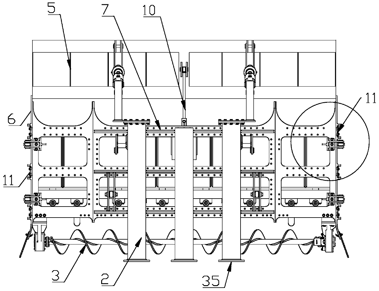
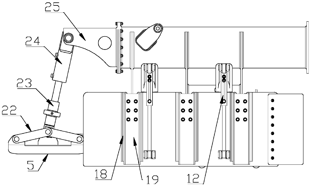
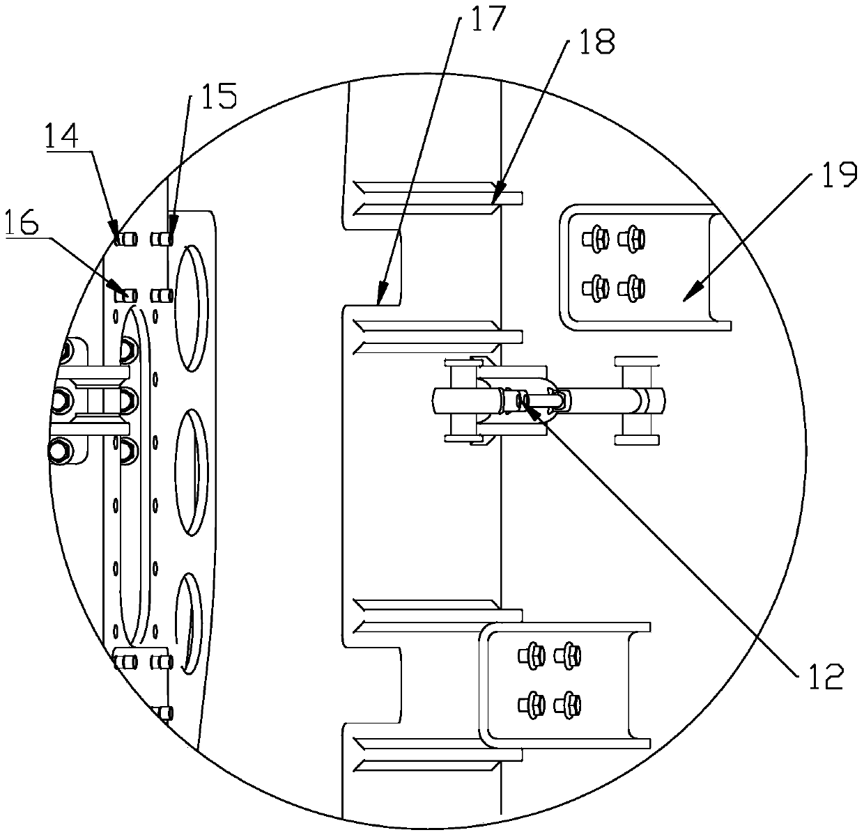
[0026] Such as Figure 1 to Figure 8 As shown in , a post-mounted slipform paver pavement slipform mold, which includes a beam frame 1, a rectangular connecting beam 2, a spiral distribution shaft 3, a vibrating rod 4, a wiper plate 5, and a side adjustment plate 6, wherein the beam frame 1 includes a square main beam frame 7, a rectangular connecting beam 2 is fixed on the top of the main beam frame 7, and connecting ports 35 are welded on the front and rear ends of the rectangular connecting beam 2 for connecting with the main frame, and fixed at the bottom of the front end of the main beam frame 7 A spiral distribution shaft 3 is provided, and a vibrating rod cylinder 8 with a piston rod protruding downwards is vertically fixed on both sides of the center of the main beam frame 7 behind the spiral distributing shaft 3. Both sides of the upper end surface of the fixed beam 9 are hinged, and the vibrating rod fixed beam 9 is arranged on the bottom of the main beam frame 7 axi...
Embodiment 2
[0032] Such as Figure 6 to Figure 12 As shown in , a post-mounted slipform paver pavement slipform mold, which includes a beam frame 1, a rectangular connecting beam 2, a spiral distribution shaft 3, a vibrating rod 4, a wiper plate 5, and a side adjustment plate 6, wherein the beam frame 1 includes a square main beam frame 7, a rectangular connecting beam 2 is fixed on the top of the main beam frame 7, and connecting ports 35 are welded on the front and rear ends of the rectangular connecting beam 2 for connecting with the main frame, and fixed at the bottom of the front end of the main beam frame 7 A spiral distribution shaft 3 is provided, and a vibrating rod cylinder 8 with a piston rod protruding downwards is vertically fixed on both sides of the center of the main beam frame 7 behind the spiral distributing shaft 3. Both sides of the upper end surface of the fixed beam 9 are hinged, and the vibrating rod fixed beam 9 is arranged on the bottom of the main beam frame 7 ax...
PUM
 Abstract
Description
Claims
Application Information