Distributed optical fiber downhole collecting device, downhole flowmeter and downhole monitoring method

A technology of distributed optical fiber and acquisition equipment, applied in wellbore/well components, measurement, earthwork drilling, etc., can solve problems such as prolonged operation time, large downhole intervention, and inability to monitor, achieve good measurement results, and increase unit space The effect of collecting points and improving resolution

Inactive Publication Date: 2015-11-11
CHINA NAT OFFSHORE OIL CORP +2
View PDF11 Cites 8 Cited by
  • Summary
  • Abstract
  • Description
  • Claims
  • Application Information

AI Technical Summary

Problems solved by technology

For the actual multi-phase flow rate, temperature, pressure and other characteristics of the underground, it is impossible to monitor online, especially when it comes to multi-layer joint production in the underground.
[0003] At present, there are also a small number of electronic and multi-instrument combination downhole flowmeters, but generally they cannot be placed downhole for long-term monitoring; in addition, they can only be used for point measurement, not distributed measurement
If it is necessary to measure the whole well, the instrument needs to be lifted and lowered frequently, which causes a lot of inconvenience in engineering, prolongs the operation time, and greatly affects the downhole intervention.

Method used


Image

  • Distributed optical fiber downhole collecting device, downhole flowmeter and downhole monitoring method
  • Distributed optical fiber downhole collecting device, downhole flowmeter and downhole monitoring method
  • Distributed optical fiber downhole collecting device, downhole flowmeter and downhole monitoring method

Examples


Embodiment Construction

[0040] In order to make the object, technical solution and advantages of the present invention more clear, the present invention will be further described in detail below in conjunction with the accompanying drawings and specific embodiments. It should be understood that the specific embodiments described here are only used to explain the present invention, not to limit the present invention.

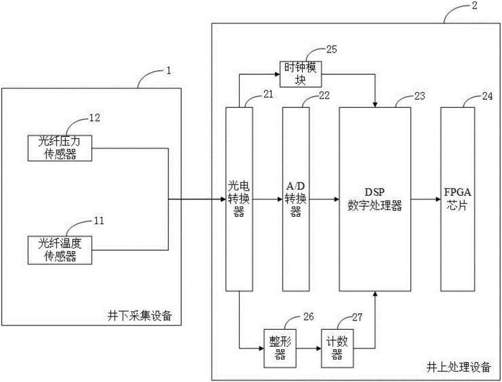
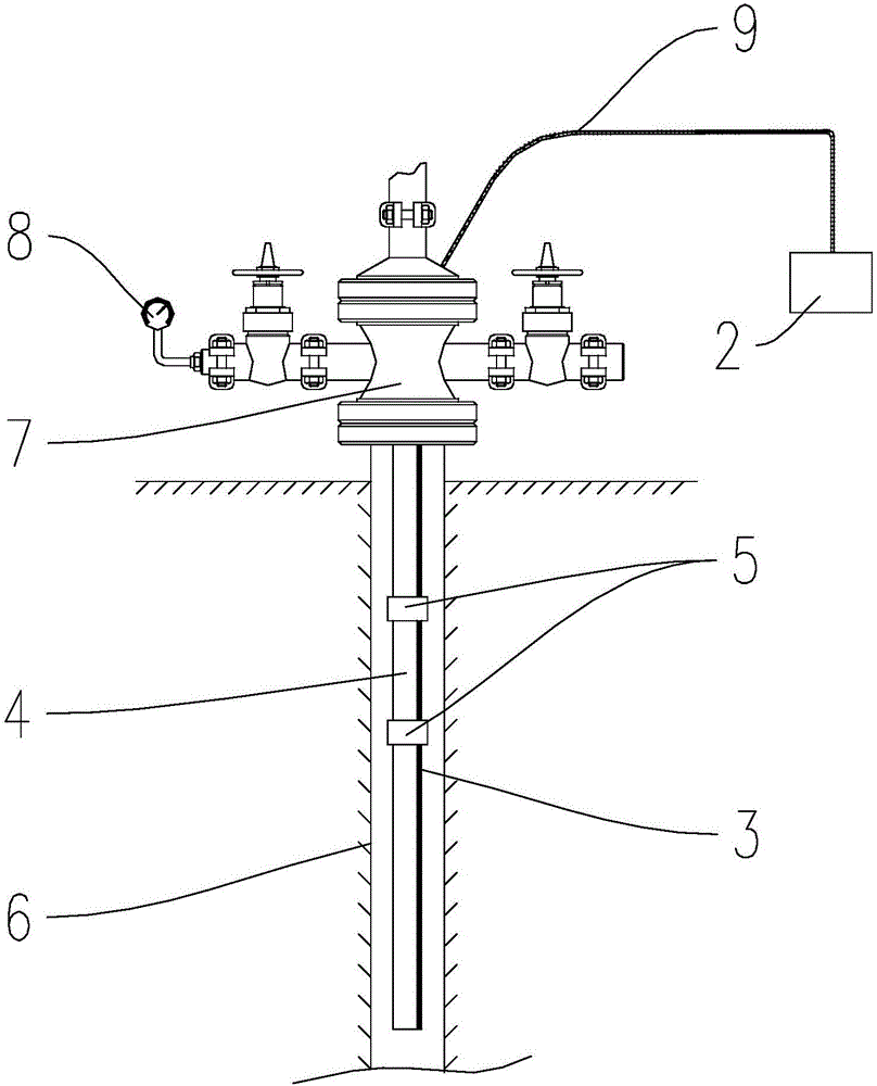
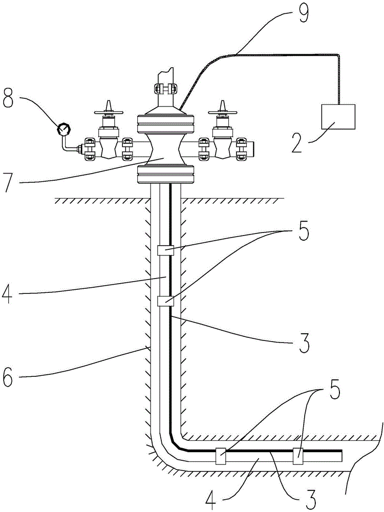
[0041] Figure 1 to Figure 3 A distributed optical fiber downhole flowmeter in the present invention is shown. The distributed optical fiber downhole flowmeter can mainly run one or more optical cables downhole and place an optical demodulator on the well. Then, the downhole temperature and pressure data are collected through the optical fiber sensor on the optical cable, and the collected downhole information is uploaded to the optical demodulator for demodulation, so as to obtain the downhole distributed multiphase flow, downhole pressure, and temperature information.

[0042] figur...


PUM


Abstract

The invention relates to a distributed optical fiber downhole collecting device. The distributed optical fiber downhole collecting device comprises a downhole string, downhole optical cables and optical fiber temperature sensors; all the downhole optical cables are wound around the downhole string into a spiral shape, or a part of the downhole optical cables are wound around the downhole string into a spiral shape, and the other part of the downhole optical cables are linearly arranged on the wall at one side of the downhole string; the optical fiber temperature sensors are integrated to the downhole optical cables and arranged in the extending direction of the downhole optical cables in a distributed mode. The invention further relates to a distributed optical fiber downhole flowmeter and a downhole monitoring method. According to the distributed optical fiber downhole collecting device, as the downhole optical cables are wound around the downhole string into the spiral shape, the number of collecting points in unit space is increased, resolution is improved, and a better measurement effect is achieved; as the optical fiber temperature sensors are arranged in the extending direction of the downhole optical cables in the distributed mode, distributed measurement can be achieved without separating downhole fluid, and full-hole measurement can be achieved without moving the downhole optical cables or the sensors.

Description

technical field [0001] The invention relates to the field of downhole monitoring, and more specifically relates to a distributed optical fiber downhole acquisition device, a downhole flowmeter and a downhole monitoring method. Background technique [0002] Under normal circumstances, when oil and gas wells are in production, they are only measured at the surface wellhead or in the oil production plant. Generally, only the flow rate is monitored, and only the underground liquid and gas production can be recorded uniformly on the ground. For the actual multi-phase flow rate, temperature, pressure and other characteristics of the downhole, online monitoring cannot be achieved, especially when it comes to downhole multi-layer commingled production. [0003] At present, there are also a small number of electronic and multi-instrument combined downhole flowmeters, but generally they cannot be placed downhole for long-term monitoring; in addition, they can only be used for point me...

Claims


Application Information

Patent Timeline
Patent Type & Authority Applications(China)
IPC IPC(8): E21B47/06E21B47/07E21B47/12E21B47/00
Inventor 闫正和黄正宇唐圣来罗东红曹琴于晓辉李四华张伟李锋高晓飞梁卫杜河泉
Owner CHINA NAT OFFSHORE OIL CORP
Why Eureka
Try Eureka