Eureka AIR delivers breakthrough ideas for toughest innovation challenges, trusted by R&D personnel around the world.

Thermal recovery system of centrifugal compressor

A centrifugal compressor, heat recovery technology, applied in mechanical equipment, machines/engines, liquid fuel engines, etc., can solve the problems of unrecovered heat energy, energy waste, etc., so as to avoid the decline of unit efficiency and avoid air blockage of the unit , to achieve the effect of environmental protection and energy saving

Inactive Publication Date: 2015-11-11
温州安腾环保节能科技有限公司
View PDF6 Cites 4 Cited by
  • Summary
  • Abstract
  • Description
  • Claims
  • Application Information

AI Technical Summary

Problems solved by technology

Air compressors are one of the machines that consume the most electricity in a general factory, and they account for a large proportion of the factory's electricity consumption. However, at present, most of the heat energy in the compressed air cannot be effectively used and directly dissipated into the atmosphere. Therefore, this part of the heat energy Not being recycled, resulting in a waste of energy

Method used


Image

  • Thermal recovery system of centrifugal compressor

Examples


Embodiment Construction

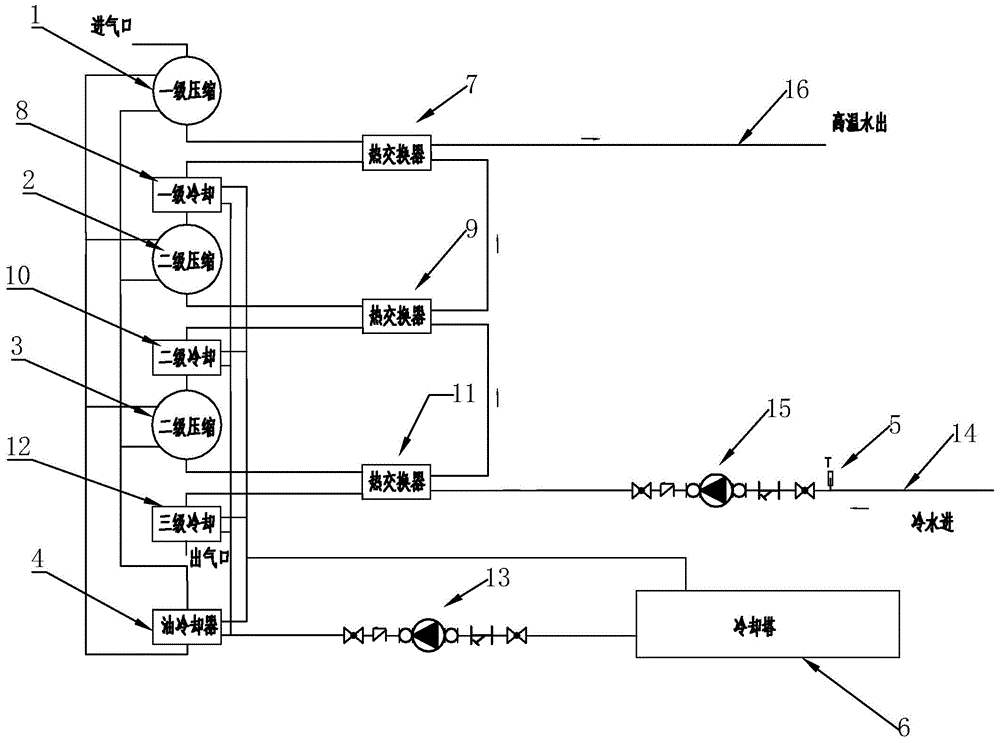
[0018] Refer to attached figure 1 The centrifugal compressor heat recovery system of the present invention will be further described in detail.

[0019] Wherein, N is greater than or equal to 2, and the number of N can be 2, 3, 4, 5.... In this embodiment, the number of N is 3 for illustration.

[0020] A heat recovery system for a centrifugal compressor, comprising a first-stage compressor host 1, a second-stage compressor host 2, a third-stage compressor host 3, an oil cooler 4, and a cooling tower 6, the first-stage compressor host 1, the second-stage compressor Both the second-stage compressor host 2 and the third-stage compressor host 3 are connected to the oil cooler 4 through pipelines, so that the first-stage compressor host 1 , the second-stage compressor host 2 and the third-stage compressor host 3 can pass through the oil cooler 4 Each independently forms a cooling circuit of the main compressor for cooling. The first-stage compressor main engine 1 is connected to ...


PUM


Abstract

The invention discloses a thermal recovery system of a centrifugal compressor. According to the technical scheme, the thermal recovery system is characterized in that N-level compression hosts are connected with an oil cooler through pipelines; an Nth-level heat exchanger is connected with a cold water pipeline and a second circulation water pump; a first-level heat exchanger is connected with a hot water pipeline; the normal-temperature water is pressurized at the second circulation water pump through the cold water pipeline and enters the Nth-level heat exchanger for heat exchange, the normal-temperature water enters a (N-1)th heat exchanger after getting out of the Nth-level heat exchanger, then enters the first-level heat exchanger after multi-time heat exchange and gets out of the first-level heat exchanger. The temperature of the normal-temperature cold water can be increased to the rated temperature, and the thermal energy produced by the compressor can be effectively recycled.

Description

technical field [0001] The invention relates to a waste heat recovery and utilization system, more specifically, it relates to a centrifugal compressor heat recovery system. Background technique [0002] The compressed air sprayed from the air compressor, the temperature of the compressed air can reach a high temperature of 200°C, usually the air compressor is cooled by an aftercooler using cooling water, and cooled by a refrigerated dryer using a refrigerant. The moisture contained in the compressed air is condensed and separated to use the compressed air. The main body of the air compressor prevents overheating by means of water cooling and air cooling. Air compressors are one of the machines that consume the most electricity in a general factory, and they account for a large proportion of the factory's electricity consumption. However, at present, most of the heat energy in the compressed air cannot be effectively used and directly dissipated into the atmosphere. Therefo...

Claims


Application Information

Patent Timeline
Patent Type & Authority Applications(China)
IPC IPC(8): F04D29/00F04D29/58
Inventor 沈长青艾水金
Owner 温州安腾环保节能科技有限公司
Why Eureka
Eureka Blog
Learn More