Lifting ring structure used for shock absorber

A shock absorber and suspension ring technology, which is applied to springs/shock absorbers, springs made of plastic materials, springs, etc., can solve the problems of hard rubber layer and reduced floating performance, so as to achieve distributed stress, uniform force, and avoid The effect of resonance

Active Publication Date: 2015-11-11
ZHEJIANG IND & TRADE VACATIONAL COLLEGE
View PDF12 Cites 0 Cited by
  • Summary
  • Abstract
  • Description
  • Claims
  • Application Information

AI Technical Summary

Problems solved by technology

[0005] Although the above-mentioned patent uses the rubber layer as the buffer layer, due to the relatively large force on the shock absorber, the rubber layer must ensure its own strength and elasticity at the same time. The smaller it is, the greater the ability to withstand pressure, the rubber layer must be harder, and the floating performance will be reduced

Method used


Image

  • Lifting ring structure used for shock absorber
  • Lifting ring structure used for shock absorber
  • Lifting ring structure used for shock absorber

Examples


Embodiment 1

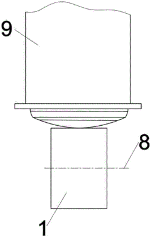
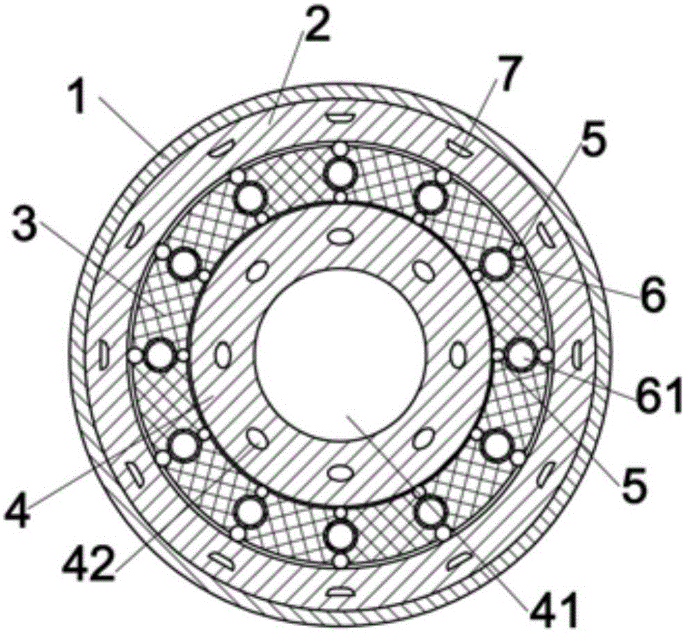
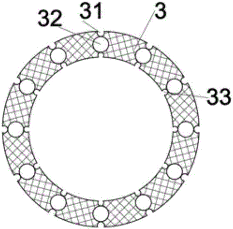
[0038] reference Figure 1 to Figure 7 ,Such as Figure 1 to Figure 3 The illustrated suspension ring structure for a shock absorber includes a pierced earring 1, which is connected to a shock absorbing cylinder 9, and a first floating sleeve 2 is provided in the pierced earring 1, and a first floating sleeve 2 is provided in the first floating sleeve 2. Two floating sleeves 3, the second floating sleeve 3 is provided with an inner sleeve 4, wherein the first floating sleeve 2 includes a number of supporting ribs 7, the number of supporting ribs 7 is 12, and the outer side of the second floating sleeve 3 is evenly distributed A number of outer grooves 31, a number of inner grooves 33 are evenly distributed inside the second floating sleeve 3, a floating sleeve hole 32 is provided between each outer groove 31 and the inner groove 33, and 32 outer grooves 31, inner grooves 33 and 32 floating sleeve holes The number is 12, the inner groove 33 and the outer groove 31 are equipped w...

Embodiment 2

[0044] reference Figure 1 to Figure 7 ,Such as figure 1 with figure 2 A suspension ring structure for a shock absorber is shown, which includes a dangling earring 1, a first floating sleeve 2, a second floating sleeve 3, an inner sleeve 4, and a plurality of buffer sleeves 6. The hanging earring 1 is fixedly connected to the absorber Below the vibrating cylinder 9, the earring 1 has a central axis 8, the wall thickness of the earring 1 is 4mm-8mm, the first floating sleeve 2 is set in the inner hole of the earring 1, and the second floating sleeve 3 is set in In the inner hole of the first floating sleeve 2, the inner sleeve 4 is sleeved in the inner hole of the second floating sleeve 3, the buffer sleeve 6 is embedded in the floating sleeve hole 32 of the second floating sleeve 3, and the buffer sleeve 6 has a buffer cavity 61. A buffer rod 62 is provided in the buffer cavity 61, and the buffer rod 62 mainly plays a role of buffering and dispersing stress.

[0045] Such as fi...

Embodiment 3

[0054] reference Figure 1 to Figure 7 ,Such as figure 1 with figure 2 A suspension ring structure for a shock absorber is shown, which includes a dangling earring 1, a first floating sleeve 2, a second floating sleeve 3, an inner sleeve 4, and a plurality of buffer sleeves 6. The hanging earring 1 is fixedly connected to the absorber Below the vibrating tube 9, the earring 1 has a central axis 8, the wall thickness of the earring 1 is 4mm-6mm, the first floating sleeve 2 is set in the inner hole of the earring 1, and the second floating sleeve 3 is set in In the inner hole of the first floating sleeve 2, the inner sleeve 4 is sleeved in the inner hole of the second floating sleeve 3, the buffer sleeve 6 is embedded in the floating sleeve hole 32 of the second floating sleeve 3, and the buffer sleeve 6 has a buffer cavity 61. A buffer rod 62 is provided in the buffer cavity 61, and the buffer rod 62 mainly plays a role of buffering and dispersing stress.

[0055] Such as figure...


PUM


Abstract

The invention discloses a lifting ring structure used for a shock absorber. The lifting ring structure comprises a lifting lug ring, a first floating sleeve, a second floating sleeve, multiple buffering sleeves and an inner sleeve. The lifting lug ring is provided with a center axis, the first floating sleeve is sleeved with an inner hole of the lifting lug ring, the second floating sleeve is sleeved with an inner hole of the first floating sleeve, the buffering sleeves are embedded inside a hole of the second floating sleeve and provided with buffering cavities, and buffering rods are arranged inside the buffering cavities. The inner sleeve is sleeved with an inner hole of the second floating sleeve and provided with a connecting hole, and after the inner sleeve is connected with an automobile, the included angle between the axis of the connecting hole and the center axis ranges from 0 degree to 5 degrees. The lifting ring structure is simple, high in bearing capacity and capable of freely floating after assembling.

Description

Technical field [0001] The invention relates to the field of shock absorbers, in particular to a suspension ring structure used for shock absorbers. Background technique [0002] At present, all automobiles are equipped with shock absorbers. The shock absorbers are mainly used to suppress the shock and the impact from the road when the spring rebounds after absorbing the shock. When passing on uneven roads, although the shock-absorbing spring can filter the vibration of the road, the spring itself will reciprocate, and the shock absorber is used to suppress the jump of this spring. If the shock absorber is too soft, the body will jump up and down. If the shock absorber is too hard, it will bring too much resistance and prevent the spring from working properly. In the process of modifying the suspension system, hard shock absorbers should be matched with hard springs, and the hardness of the spring is closely related to the weight of the vehicle, so heavier cars generally use har...

Claims


Application Information

Patent Timeline
Patent Type & Authority Applications(China)
IPC IPC(8): F16F1/38
CPCF16F1/38F16F1/3842F16F1/3863
Inventor 王文深李晓星
Owner ZHEJIANG IND & TRADE VACATIONAL COLLEGE
Why Eureka
Try Eureka