
Indoor air quality optimizing system

A technology of air quality and air purification devices, which is applied in the field of air purification, can solve the problems of air optimization effects that cannot achieve the expected results, waste of resources, etc., and achieve the effects of reducing resource and cost constraints, saving resources, and increasing oxygen content

Inactive Publication Date: 2015-11-11
深圳维安云联技术有限公司
View PDF12 Cites 6 Cited by
  • Summary
  • Abstract
  • Description
  • Claims
  • Application Information

AI Technical Summary

Problems solved by technology

[0002] With the improvement of people's living standards, the indoor air quality optimization system, as a product that can effectively improve the cleanliness of the air, is more and more applied to various places, especially some places with relatively harsh environments; the existing indoor air quality The quality optimization system either only has the function of air filtration and purification, and the purification filter material is a consumable, which must be replaced after a period of use, which is a serious waste of resources; pressure, to send out the indoor dirty air through the gaps between doors and windows, but this method requires additional energy consumption to heat or cool the air sucked in from the outside to keep the indoor air temperature constant, which is a serious waste of resources; in addition, the current use of The working mode of air purification device and oxygen concentrator is a single combination of one air purification device and one oxygen concentrator, so that when the oxygen supply of the oxygen concentrator cannot meet the demand, the effect of air optimization cannot reach the expected Effect

Method used


Image

  • Indoor air quality optimizing system
  • Indoor air quality optimizing system
  • Indoor air quality optimizing system

Examples


Embodiment Construction

[0021] In order to make the purpose, technical solutions and advantages of the embodiments of the present invention clearer, a clear and complete description will be made below in conjunction with the technical solutions in the embodiments of the present invention. Obviously, the described embodiments are part of the embodiments of the present invention, and Not all examples. Based on the embodiments of the present invention, all other embodiments obtained by persons of ordinary skill in the art without making creative efforts belong to the protection scope of the present invention.

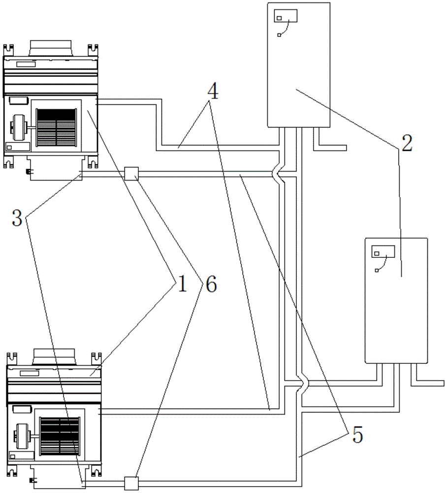
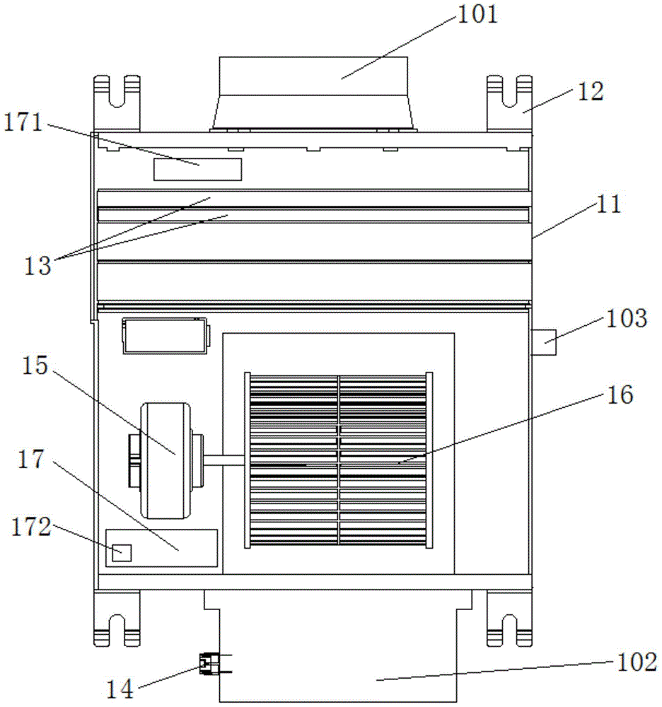
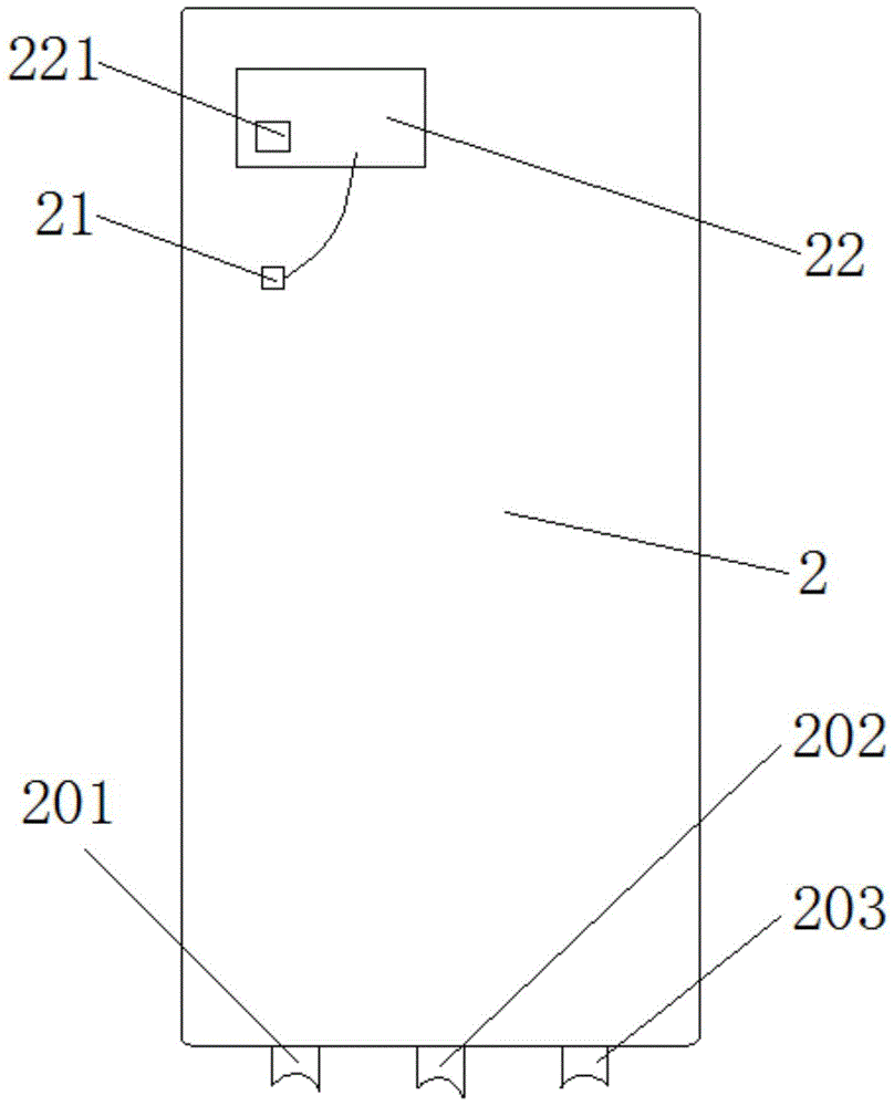
[0022] The air quality optimization system of the preferred embodiment of the present invention is as figure 1 shown, see also figure 2 , image 3 and Figure 4 , including one or more air purification devices 1 and one or more oxygen generators 2 for filtering and purifying air and generating negative ions or plasma; Oxygen supply port 3, air cleaning device 1 includes housing 11, combined ...


PUM


Abstract

The invention relates to an indoor air quality optimizing system. The indoor air quality optimizing system comprises one or more air purification devices used for filtering and purifying air and generating anions or plasma and one or more oxygenators. The indoor air quality optimizing system further comprises a first oxygen port used for conveying oxygen separated by the oxygenators to the indoor part. Each air purification device comprises a shell, an installing plate, a combined filtering module used for purifying and filtering air, an ion generator, a motor and blades. The oxygenators are provided with sensors used for detecting the pressure of oxygen in oxygen supply pipelines. The oxygenators are further provided with first control plates. The sensors are electrically connected with the first control plates. The air purification devices are provided with second control plates. One air purification device can be connected with and control one or more oxygenators. One oxygenator is connected with one or more air purification devices. The problems of fast oxygen consumption and the slow occasion oxygen supply are solved; meanwhile, the indoor air quality optimizing system can be installed in multiple rooms at the same time; and intelligent starting or stopping of the oxygenators is achieved during using, and the resource utilization rate is high.

Description

technical field [0001] The invention relates to the technical field of air purification, and more specifically relates to an indoor air quality optimization system. Background technique [0002] With the improvement of people's living standards, the indoor air quality optimization system, as a product that can effectively improve the cleanliness of the air, is more and more applied to various places, especially some places with relatively harsh environments; the existing indoor air quality The quality optimization system either only has the function of air filtration and purification, and the purification filter material is a consumable, which must be replaced after a period of use, which is a serious waste of resources; pressure, to send out the indoor dirty air through the gaps between doors and windows, but this method requires additional energy consumption to heat or cool the air sucked in from the outside to keep the indoor air temperature constant, which is a serious w...

Claims


Application Information

Patent Timeline
IPC IPC(8): F24F3/16F24F11/02
CPCF24F3/16F24F11/89F24F8/108F24F8/30F24F8/60Y02B30/70
Inventor 彭书涛陈志刚骆海
Owner 深圳维安云联技术有限公司
Learn More