Separation type airflow drying kettle

An airflow drying and separation technology, applied in the direction of non-progressive dryers, drying solid materials, drying gas arrangement, etc., can solve the problems of reduced drying efficiency, inconvenient collection, and troubles for operators, and achieves convenient cleaning and maintenance. Ease of collection and improvement of drying efficiency

Inactive Publication Date: 2015-11-11
张洪飞
View PDF0 Cites 9 Cited by
  • Summary
  • Abstract
  • Description
  • Claims
  • Application Information

AI Technical Summary

Problems solved by technology

[0002] The main principle of the airflow drying kettle is to dry the material through the airflow, and take away the moisture in the material through the high temperature and airflow, so as to promote the rapid drying of the material. In the actual operation process, because the wet material is generally stored with a screen, the wet material It is easy to accumulate in the screen holes of the screen, which not only affects the ventilation effect of the screen itself, but also reduces the drying efficiency of the device. At the same time, the dried materials are easy to block the screen opening, making it diff

Method used


Image

  • Separation type airflow drying kettle

Examples


Embodiment 1

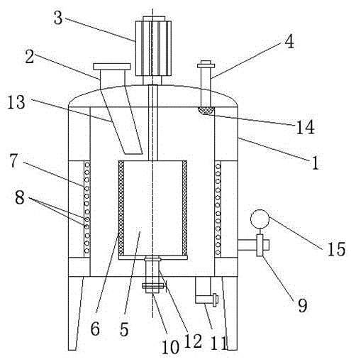
[0014] Embodiment 1: as figure 1 A separate airflow drying kettle is shown, the airflow drying kettle is a cylindrical shell 1, the top of the shell 1 is provided with a feeding port 2 and a transmission motor 3, and the middle part of the shell 1 is provided with a cylindrical Shaped drying cylinder 5, the top of the drying cylinder 5 is provided with a rotating shaft fixedly connected to the transmission motor 3, the side wall of the drying cylinder 5 is composed of a filter screen 6, the housing 1 is connected with the drying cylinder 5 There are two vertical air blast pipelines 7 on the inner wall of the same height, and multiple air outlets 8 are evenly distributed on the different heights of the air blast pipelines 7, and the outer side of the housing 1 is provided with an air intake pipeline 9 is connected to the blast pipeline 7, the bottom of the housing 1 is provided with a light material collection port 11 and a heavy material collection port 10, and the heavy mater...

Embodiment 2

[0015] Embodiment 2: as figure 1 As shown, the light material collection port 11 is arranged at the bottom of the housing 1, and the light material collection port 11 is connected to the vacuum pump through a pipeline; All the materials are discharged from the drying cylinder 5 and enter the shell 1. After the blast pipeline 7 stops working, the small particles floating in the shell 1 gradually deposit on the bottom of the shell 1 and pass through the light material collection port 11. Combined with the vacuum pump, it is convenient for the collection of small particles and light materials.

Embodiment 3

[0016] Embodiment 3: as figure 1 As shown, the bottom of the feeding port 2 is provided with a feed pipe 13 connected to the top of the drying drum 5, and the feed pipe 13 is an inclined feed pipe; through the feed pipe 13, the material is conveniently directly added to the drying drum 5, and the material is in the drying drum 5. The dual action of centrifugal force and airflow enters the drying cylinder 5 to further improve the drying efficiency of materials.


PUM


Abstract

The invention discloses a separation type airflow drying kettle. The drying kettle is a cylindrical shell, and a cylindrical drying cylinder is arranged in the middle of the shell; a rotating shaft is arranged on the top of the drying cylinder and is fixedly connected to a transmission motor, and the side wall of the drying cylinder is composed of a filtering screen; two perpendicular blast pipelines are arranged on the inner wall, the same as the drying cylinder in height, of the shell, and a plurality of air outlets are evenly distributed in the positions, with the different heights, of the blast pipelines; an air inlet pipeline is arranged on the outer side of the shell and is connected to the blast pipelines, and a light-material collecting opening and a heavy-material collecting opening are formed in the bottom of the shell; and the heavy-material collecting opening is fixedly connected to the bottom of the drying cylinder through an extending pipe and a rotating bearing. Through double effects of airflow and centrifugal force, the problem that damp materials are stuck to the filter screen is solved, and meanwhile, the materials in the drying cylinder can be separated; and the small-particle materials are discharged out of the drying cylinder along with the airflow or under the effect of the centrifugal force, and the materials with different masses or volumes can be conveniently collected.

Description

technical field [0001] The invention relates to the field of material drying equipment, in particular to an airflow drying kettle that can facilitate material separation. Background technique [0002] The main principle of the airflow drying kettle is to dry the material through the airflow, and take away the moisture in the material through the high temperature and airflow, so as to promote the rapid drying of the material. In the actual operation process, because the wet material is generally stored with a screen, the wet material It is easy to accumulate in the screen holes of the screen, which not only affects the ventilation effect of the screen itself, but also reduces the drying efficiency of the device. At the same time, the dried materials are easy to block the screen opening, making it difficult to clean and collect. [0003] At the same time, for the ordinary airflow drying kettle on the market, its function is relatively single, and it can only be used for the dr...

Claims


Application Information

Patent Timeline
IPC IPC(8): F26B11/08F26B21/00F26B25/00
Inventor 张洪飞
Owner 张洪飞
Why Eureka
Try Eureka