
Valve automatic detection equipment

An automatic detection and valve technology, applied in the direction of detecting the appearance of fluid at the leakage point, measuring devices, testing of mechanical parts, etc., can solve problems such as low work efficiency, inability to realize automatic detection, and inability to detect valves one by one, so as to improve The effect of work efficiency

Active Publication Date: 2015-11-11
江苏捷迈斯阀门有限公司
View PDF4 Cites 19 Cited by
  • Summary
  • Abstract
  • Description
  • Claims
  • Application Information

AI Technical Summary

Problems solved by technology

[0004] In order to overcome the shortcomings of the existing valve detection devices, such as low working efficiency, inability to detect valves one by one, and inability to realize automatic detection, the present invention provides an automatic valve detection device. Combined with reciprocating movement, automatic detection is realized under the control of PLC, which effectively improves work efficiency, can detect valves one by one, and automatically separate unqualified valves, which meets the needs of automatic valve production

Method used


Image

  • Valve automatic detection equipment
  • Valve automatic detection equipment
  • Valve automatic detection equipment

Examples


Embodiment Construction

[0027] The present invention will be further described below in conjunction with accompanying drawing:

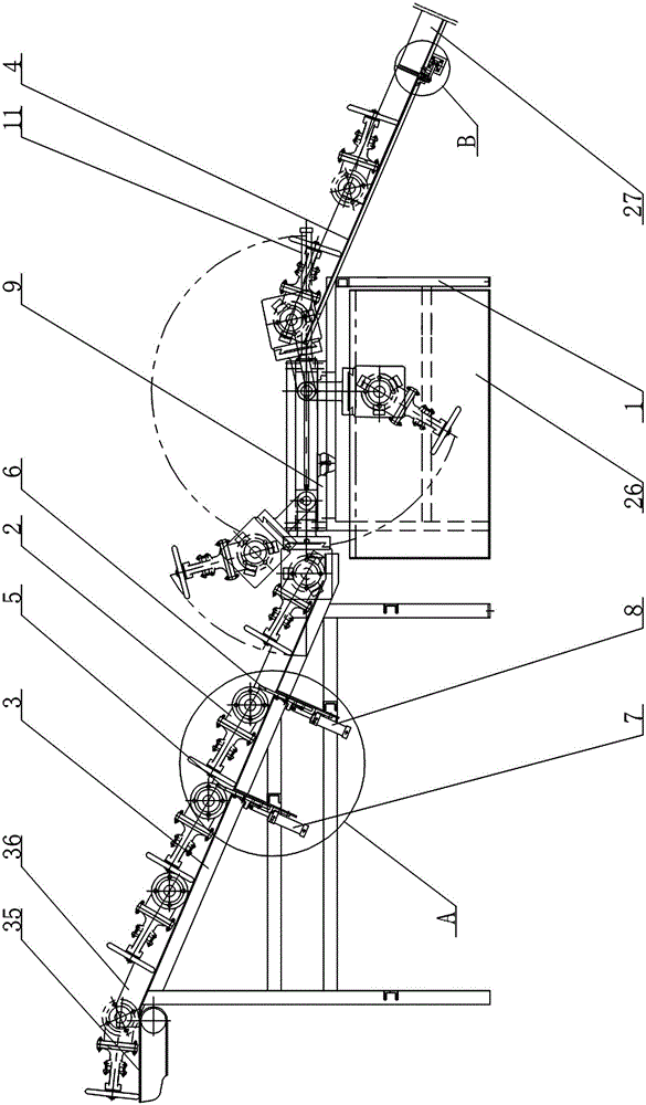
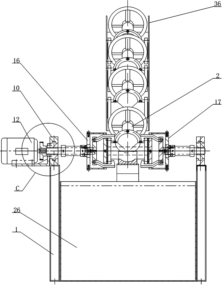
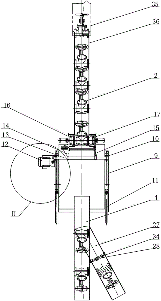
[0028] Depend on Figure 1 to Figure 12As shown, the valve automatic detection equipment includes a frame 1, and the two sides of the frame 1 are respectively provided with a valve bracket 3 to be inspected and a discharge slide 4 for storing the valve 2, and a valve bracket 3 to be inspected and a discharge slide 4. The upper end surface of the valve is inclined in the same direction. A blocking gate 5 and a release gate 6 are provided under the valve bracket 3 to be inspected. A valve 2 can be stored between the barrier gate 5 and the release gate 6. The barrier gate 5 and the The release gate 6 is respectively connected to the barrier cylinder 7 and the release cylinder 8; two parallel guide rails 9 are fixed on the frame 1, and the two guide rails 9 are equipped with sliders 10, and the two sliders 10 run synchronously with the two The horizontal cylinder 11 is connect...


PUM


Abstract

The invention relates to valve automatic detection equipment, and mainly solves problems that existing valve detection devices are low in work efficiency and cannot detect valves one by one and cannot realize automatic detection. The valve automatic detection equipment is characterized in that a rotating shaft (13) is installed between two slide blocks (10) and driven by two synchronous operating horizontal cylinders (11). A left swing arm (14) and a right swing arm (15) are respectively provided with a left clamp (16) and a right clamp (17) which are corresponding. A clamping cylinder (19) drives a claw (20) to open and close. The lower end of a material discharge carriage (4) is provided with a separating slideway (27). With combination of forward and backward rotation of a motor and reciprocating movement of the horizontal cylinders, automatic detection is realized under the control of a PLC so that work efficiency is effectively enhanced, the valves can be detected one by one, the defective valves can be automatically separated and thus the requirement for automatic production of the valves can be met.

Description

technical field [0001] The invention relates to a device for detecting pressure resistance of a valve body, detecting leakage after opening and closing parts are closed, and detecting upper sealing performance, in particular to an automatic detection device for valves. Background technique [0002] The valve is a control device in the medium conveying system. It has functions such as cut-off, regulation, flow diversion, reverse flow prevention, pressure stabilization, flow diversion or overflow pressure relief. It can be used to control air, water, steam, various corrosive media, mud, The flow of various types of fluids such as oil, liquid metal and radioactive media. The sealing performance of the valve refers to the ability of each sealing part of the valve to prevent the leakage of the medium, which is the most important technical performance index of the valve. There are three main sealing parts of the valve: 1. The contact between the opening and closing parts and the ...

Claims


Application Information

Patent Timeline
Patent Type & Authority Applications(China)
IPC IPC(8): G01M3/28G01M3/08G01M13/00
Inventor 沈永松
Owner 江苏捷迈斯阀门有限公司
Learn More