Multifunctional terahertz wave imaging system and imaging method

A terahertz wave imaging, multi-functional technology, applied in the field of terahertz wave imaging, can solve problems such as no application, and achieve the effect of reducing cost, reducing time, and avoiding replacement methods

Active Publication Date: 2015-11-11
UNIV OF SHANGHAI FOR SCI & TECH
View PDF4 Cites 16 Cited by
  • Summary
  • Abstract
  • Description
  • Claims
  • Application Information

AI Technical Summary

Problems solved by technology

Currently, there is no application for this

Method used


Image

  • Multifunctional terahertz wave imaging system and imaging method
  • Multifunctional terahertz wave imaging system and imaging method
  • Multifunctional terahertz wave imaging system and imaging method

Examples


Embodiment 1

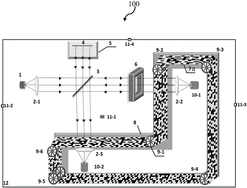
[0025] figure 1 It is a schematic structural diagram of the multifunctional terahertz wave imaging system in the first embodiment.

[0026] Such as figure 1 As shown, the multifunctional terahertz wave imaging system 100 is composed of a terahertz wave transmitting part, a beam splitting part, a planar image acquisition part, a coherent cross-sectional image acquisition part, an imaging processing and display part, and a control part.

[0027] The terahertz wave emitting part includes a terahertz wave emitter 1 and a light dispersing unit 2-1, the terahertz wave emitter 1 is used for emitting terahertz waves, and the light dispersing unit 2-1 is used for dispersing the terahertz waves into parallel waves.

[0028] The beam splitter 3 is a quartz sheet or a glass sheet coated with an ITO conductive layer, which is arranged on the optical path of the terahertz wave, and is used to split the terahertz wave into a first beam and a second beam perpendicular to each other. Accordi...

Embodiment 2

[0054] In the second embodiment, the same structures as those in the first embodiment are given the same symbols, and the same descriptions are omitted.

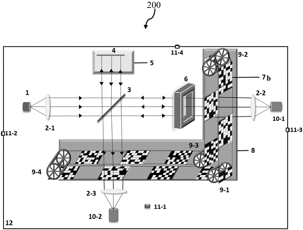
[0055] figure 2 It is a schematic structural diagram of the multifunctional terahertz wave imaging system in the second embodiment.

[0056] Such as figure 2 As shown, the synthetic encoding mask ring 7b in the multifunctional terahertz wave imaging system 200 is composed of mask squares of equal size and transparent terahertz wave squares arranged alternately, wherein the mask square is a flexible circuit board, and the terahertz wave transparent squares are arranged alternately. It is a flexible plastic plate that can transmit terahertz waves. In the synthetic encoding mask ring, the opposite to the mask square is a permeable terahertz wave block, therefore, the two beams of terahertz waves used for imaging pass through the mask ring twice, and each beam of terahertz waves passes through the mask When the ring passes ...

Embodiment 3

[0059] In the third embodiment, the same structures as those in the first embodiment are given the same symbols, and the same descriptions are omitted.

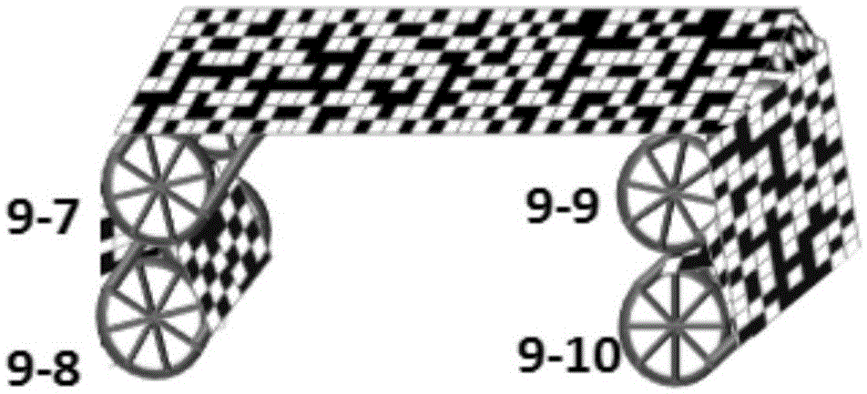
[0060] image 3 It is a schematic structural diagram of the roll-to-roll synthetic coding mask module in the third embodiment.

[0061] Such as image 3 As shown, the first spatial modulation unit and the second spatial modulation unit are the same, and both are roll-to-roll synthetic coding mask modules. The reel-type synthetic coding mask module includes two sliding wheel sets arranged horizontally and at a certain distance apart, and the two sliding wheel sets respectively include two vertically arranged sliding wheels 9-7 to 9-10, wherein the sliding wheels 9-8 and sliding wheels 9-10 act as spools around which a flexible synthetic code mask is wound. When the test starts, all four sliding wheels rotate clockwise (or counterclockwise), and the synthetic coding mask ring on sliding wheel 9-8 is driven through 9-7, 9-9 a...


PUM


Abstract

The invention provides a multifunctional terahertz wave imaging system. The imaging system includes a terahertz wave emission part, which is used for emitting terahertz waves and diverging the terahertz wave into parallel waves; a beam splitting part, which is used for splitting the terahertz waves into a first light beam and a second light beam that are mutually perpendicular; a planar image acquisition part, which is disposed on the light path of the first light beam to acquire the planar terahertz wave image information of a to-be-detected sample; a coherent cross-section image acquisition part, which is disposed on the light path of the second light beam to acquire the terahertz wave image information of the to-be-detected sample at different depth cross-sections; an imaging processing and display part, which is used for processing the image information, constructing the terahertz planar image and coherent cross-section images of the to-be-detected sample, and at the same time synthesizing all the coherent cross-section images to obtain a terahertz three-dimensional image of the to-be-detected sample; and a control part. Specifically, the planar image acquisition part and the coherent cross-section image acquisition part both have synthetic encoding masks, and through mask conversion, a sample information encoding process can be completed.

Description

technical field [0001] The invention belongs to the field of terahertz wave imaging, and in particular relates to a multifunctional terahertz wave imaging system that takes into account both plane transmission and reflection tomography. Background technique [0002] Terahertz wave is an electromagnetic wave band between infrared and microwave, usually 0.1THz ~ 10THz is defined as "THzGap", that is, terahertz band. Electromagnetic waves in this band have both the directionality of visible light and the penetrating ability of microwaves. Because of the above two advantages, terahertz wave has become one of the best choices for non-destructive detection, and has become a parallel option for X-ray imaging in some specific fields. [0003] At present, the research of terahertz wave imaging mainly focuses on two aspects, one is terahertz wave planar imaging, and the other is terahertz wave coherence tomography. Terahertz wave planar imaging is divided into transmission and refle...

Claims


Application Information

Patent Timeline
Patent Type & Authority Applications(China)
IPC IPC(8): G01N21/3586G01V8/10
CPCG01N21/3581
Inventor 卜婷陈克坚倪丹丹白杨
Owner UNIV OF SHANGHAI FOR SCI & TECH
Why Eureka
Try Eureka