
Modeling method for short time freewheeling reverse recovery of spike voltage of power diode

A technology of power diodes and reverse recovery, applied in electrical digital data processing, special data processing applications, instruments, etc., can solve problems affecting the reliability of power electronic devices, hidden dangers of reliable operation of power electronic devices, breakdown failure of switching devices, etc. question

Active Publication Date: 2015-11-11
NAVAL UNIV OF ENG PLA
View PDF4 Cites 8 Cited by
  • Summary
  • Abstract
  • Description
  • Claims
  • Application Information

AI Technical Summary

Problems solved by technology

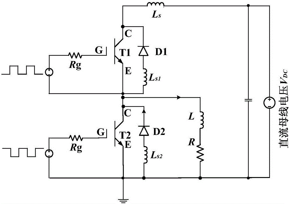
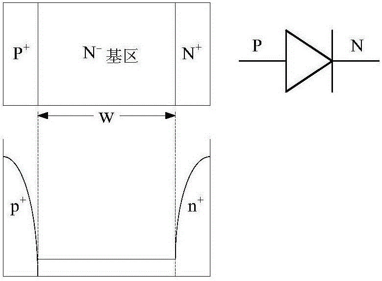
[0004] Power diode reverse recovery peak voltage refers to that during the process of the diode from turning on to turning off, due to the discharge of the remaining carriers stored in the internal base of the diode, it will continue to increase in the reverse direction after the forward current of the diode becomes zero, and then With the discharge of the charge stored in the base area, the reverse current decreases and eventually becomes zero. Therefore, the rate of change of the reverse current will generate a voltage spike on the stray inductance of the diode circuit, which will cause the breakdown of the switching device in severe cases. Failure, affecting the operational reliability of power electronic devices
With the increase of the voltage and current level of the power device and the increase of the frequency of the converter device, the freewheeling time of the freewheeling diode will also increase, reaching the level of microseconds or even ten microseconds. Occurrence in the state, there is a certain hidden danger to the reliable operation of power electronic devices

Method used


Image

  • Modeling method for short time freewheeling reverse recovery of spike voltage of power diode
  • Modeling method for short time freewheeling reverse recovery of spike voltage of power diode
  • Modeling method for short time freewheeling reverse recovery of spike voltage of power diode

Examples


Embodiment Construction

[0047] The present invention will be further described in detail below in conjunction with the accompanying drawings and specific embodiments. However, it does not constitute a limitation to the present invention, and is only used as an example. At the same time, the advantages of the present invention will become clearer and easier to understand through the description.

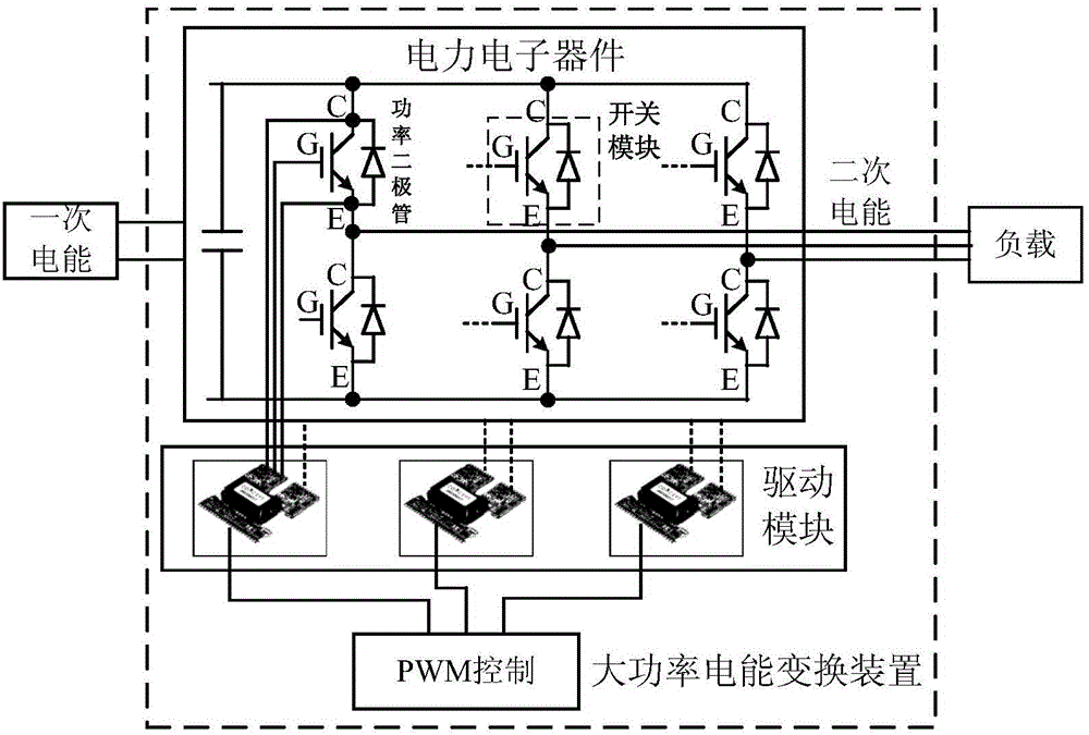
[0048] The power diode reverse recovery peak voltage of the present invention all occurs in the bridge switching of high-power power electronic devices, such as figure 2 In the schematic diagram of the high-power electric energy conversion device shown, the two sets of switches in the same bridge are switched off alternately. Only when one set of switches is turned off, the power diodes in the other set of switches will turn on freewheeling to provide power discharge. circuit.

[0049] The initial condition of the modeling is that the freewheeling time of the power diode is on the order of hundreds of nan...


PUM


Abstract

The present invention relates to the field of power electronic device modeling, and particularly relates to a modeling method for short time freewheeling reverse recovery of a spike voltage of a power diode. The method comprises: based on the basic structure of a power diode and the operation principles of semiconductor physics and power electronic converter devices, by building a physical model and a behavior model of turn-on and turn-off transient states of the power diode, and through physical mechanism analysis of turn-on and turn-off transient states of the power diode, obtaining a relationship between key parameters of the two models, so as to establish a modeling method of a hybrid model based on the physical model and the behavior model; and based on the hybrid model of the turn-on and turn-off transient states of the power diode, establishing a model of reversely recovering a spike voltage under a short time freewheeling condition. The method provided by the present invention can not only ensure model accuracy but also reduce model complexity.

Description

technical field [0001] The invention relates to the modeling field of power electronic devices, in particular to a modeling method for short-time freewheeling reverse recovery peak voltage of a power diode. Background technique [0002] Power diode (powerdiode) is the core power electronic device widely used in modern power electronic devices to achieve high-efficiency power conversion and control. The power diode plays the role of providing circuit energy discharge during the switching process of the module, so it is also called a freewheeling diode, which can prevent dangerous overvoltage when the inductive load circuit is hard-off. [0003] The power diode and the fully-controlled switching device IGBT form a switching module together. For a long time, the research on switching devices has been deepened, while the role of diodes has been ignored. Until recent years, with the increase in the capacity and frequency of power conversion devices , the fast switching of circui...

Claims


Application Information

Patent Timeline
IPC IPC(8): G06F17/50
Inventor 罗毅飞肖飞汪波刘宾礼夏燕飞熊又星孙文王钰
Owner NAVAL UNIV OF ENG PLA
Learn More