Preassembling mechanism for motor end cap

A motor end cover and pre-installation technology, which is applied in the direction of electromechanical devices, manufacturing motor generators, electrical components, etc., can solve the problems of laborious automation, achieve a good degree of automation, realize automatic assembly, and reduce labor costs.

Active Publication Date: 2015-11-11
TONGXIANG SHENGHUI PRECISION MACHINERY
View PDF10 Cites 21 Cited by
  • Summary
  • Abstract
  • Description
  • Claims
  • Application Information

AI Technical Summary

Problems solved by technology

[0003] The invention provides a motor end cover pre-installation mechanism capable of assembling the motor end cover on the motor casing, which solves the problems of manual assembly of the motor end cover, which is laborious and has a low degree of automation

Method used


Image

  • Preassembling mechanism for motor end cap
  • Preassembling mechanism for motor end cap
  • Preassembling mechanism for motor end cap

Examples


Embodiment 1

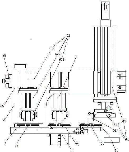
[0029] Embodiment one, see figure 2 , a motor end cover pre-installation mechanism, including a frame 2, a suspension plate 65, a first manipulator 62, a second manipulator 63 and a third manipulator 64.

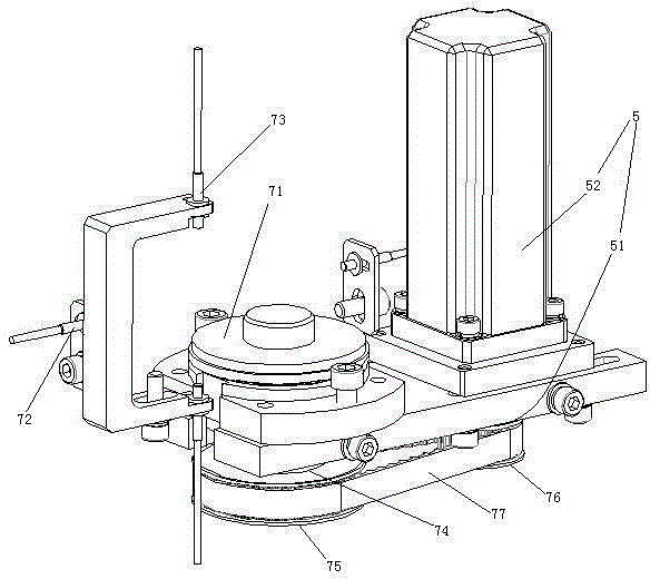
[0030] The right side of the frame 2 is provided with a motor housing fixing structure 21 . The motor housing fixing structure 21 is a manipulator, and of course it is possible to use a suction cup for adsorption and fixation, or a clamp for clamping and fixing. The frame 2 is also provided with a loading level 22 , a motor end cover support block 61 , a motor end cover alignment mechanism 7 and a fourth drive mechanism 66 . The motor end cover alignment mechanism 7 includes a first motor end cover support block 71 . The upper material level 22, the first motor end cover support block 71, the motor end cover support block 61 and the motor housing fixing structure 21 are distributed sequentially from left to right. The first motor end cover support block 71 is located bet...

Embodiment 2

[0036] Embodiment two, the difference with embodiment one is:

[0037] see Figure 5 , the motor shaft 51 is supported on the motor housing 52 through two bearings 55 . An oil filling chamber 56 is formed between the motor housing 52 and the two bearings 55 . A first gear 58 and a second gear 57 are arranged in the oil filling cavity 56 . The first gear 58 and the second gear 57 mesh together. The first gear 58 is connected with the motor shaft 51 . The second gear 57 is rotationally connected with the motor housing 52 through a short shaft 571 .

[0038] see Figure 6 , the first gear 58 is provided with a refueling mechanism 8 . The number of refueling mechanisms 8 is equal to the number of teeth of the first gear 58 .

[0039] see Figure 7 , The refueling mechanism 8 includes an oil outlet 81 , an air supply port 82 , a sealing head 83 , a first spring 84 , a cylinder 85 and a piston 86 . The oil outlet 81 and the air supply port 82 of the same fueling mechanism a...

Embodiment 3

[0044] Embodiment three, the difference with embodiment two is:

[0045] see Figure 9 , The rack 2 is provided with a tilting self-power-off switch 9 . The tilt self-cutting switch 9 includes a shell 91 and a connecting pin 92 . The shell 91 is fixedly connected with the frame 2 . The power supply of the electrical components on the present invention is introduced through inclination self-cutting switch 9.

[0046] see Figure 10 , The tilt self-disconnecting switch 9 also includes a power-disconnecting spring 93 , a conductive sheet 94 , a weight guide cavity 95 , a weight 96 , a swing arm 97 and a barb 98 .

[0047] The shell 91 is made of insulating material, specifically made of plastic. The shell 91 is connected with the frame 2 together. The housing 91 is provided with an assembly cavity 911 . A recess 915 is formed in the middle of the bottom wall of the assembly cavity 911 .

[0048] There are two connecting pins 92. The two connecting pins 92 are distributed...


PUM


Abstract

The invention relates to the technical field of motor production equipment. A preassembling mechanism for a motor end cap comprises a frame with a discharging position, a motor housing fixing structure, a second motor end cap supporting block and a motor end cap aligning mechanism with a first motor end cap supporting block, a first manipulator shifting the motor end cap from the discharging position to the first motor end cap supporting block, a second manipulator shifting the motor end cap from the first motor end cap supporting block to the second motor end cap supporting block and a third manipulator shifting the motor end cap from the second motor end cap supporting block and installing onto a motor housing in the motor housing fixing structure. The invention provides a preassembling mechanism for preassembling the motor end cap onto the motor housing, and solves the problem that manual assembling of motor end cap is labor consuming and is low in automation level.

Description

technical field [0001] The invention relates to equipment for motor production, in particular to a pre-installation mechanism for a motor end cover. Background technique [0002] The motor includes a housing, electronics disposed in the housing, and a rotor located in the stator. The rotor is connected to a rotating shaft (motor shaft), at least one end of the housing is connected to a motor end cover, and the rotating shaft passes through the motor end cover. Promptly disclose a kind of motor in the patent document of Chinese Patent Publication No. CN10453902, titled "Permanent Magnet Brushless Motor with Dust Structure on Rotor". Motor end caps such as figure 1 As shown, the motor end cover 1 includes an end cover body 11, and a shaft hole 12 is arranged in the middle of the end cover body 11. The inner end surface of the end cover body 11 protrudes inwardly to form a mounting boss 13, and the mounting boss 13 and the end cover body 11 forms an annular step 14, and the e...

Claims


Application Information

Patent Timeline
Patent Type & Authority Applications(China)
IPC IPC(8): H02K15/14
Inventor 方勇王新生陈林生徐卫宏刘小雄
Owner TONGXIANG SHENGHUI PRECISION MACHINERY
Why Eureka
Try Eureka