Casting tool fixture

A technology of fixtures and castings, which is applied in the field of casting production auxiliary tools, can solve problems such as low efficiency, high scrap rate, and long adjustment time, and achieve the effects of accurate installation and positioning, high production efficiency, and high degree of automation

Inactive Publication Date: 2015-11-18
WUXI LEHUA AUTOMATION TECH
View PDF6 Cites 7 Cited by
  • Summary
  • Abstract
  • Description
  • Claims
  • Application Information

AI Technical Summary

Problems solved by technology

The accuracy of manual positioning adjustment is low, generally requires multiple operations, long adjustment time and low efficiency
[0010] 2. During the processing, when the clamping and loosening of the corner oil cylinder occurs, and the pressure detected by the pressure sensor is lower than the set value, the microcomputer controller can only give an early warning. When there is no operator on site, the equipment will automatically stop. When the site is long When no one is on duty or repairing for a long time, the equipment will also be at a standstill, which will seriously affect the processing efficiency of production
[0013] In the above patent application, since each positioning block can move axially, the purpose of positioning reference is lost. After the casting is clamped, it is prone to tilting during subsequent operations, resulting in a high scrap rate.

Method used


Image

  • Casting tool fixture

Examples


Embodiment Construction

[0026] The present invention will be further described in detail below in conjunction with the accompanying drawings and specific preferred embodiments.

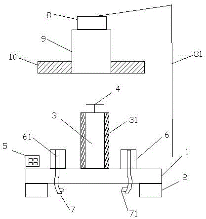
[0027] Such as figure 1 As shown, a casting fixture includes a PLC 5 , an air pipe 7 , a base plate 1 , a corner oil cylinder 3 arranged in the center of the base plate 1 , a motor 8 , a hollow motor shaft 9 and an annular electromagnet 10 .

[0028] The bottom of the bottom plate 1 is provided with a plurality of legs 2 , and a plurality of reference positioning blocks 6 are evenly arranged on the bottom plate 1 located on the outer periphery of the corner oil cylinder 3 .

[0029] The outer periphery of the corner oil cylinder 3 is covered with a non-magnetic layer 31 , and the top of the corner oil cylinder 3 is provided with an automatic locking handle 4 connected to the PLC 5 .

[0030] Each reference positioning block 6 is provided with an axial through hole 61 connected with the air pipe 7 , and each air pipe 7 is pr...


PUM


Abstract

The invention discloses a casting tool fixture which comprises a PLC (Programmable Logic Controller), air pipes, a bottom plate, and a corner oil cylinder that is arranged in the center of the bottom plate, wherein a plurality of reference locating blocks are uniformly arranged on the bottom plate positioned at the periphery of the corner oil cylinder; each reference locating block is internally provided with an axial through hole connected with one air pipe; a pressure sensor connected with the PLC is arranged on each air pipe; an automatic locking handle connected with the PLC is arranged at the top of the corner oil cylinder; a hollow motor shaft with the height capable of being adjusted is coaxially arranged over the corner oil cylinder; the inner diameter of the hollow motor shaft is greater than the outer diameter of the corner oil cylinder; an annular electromagnet is mounted on the outer periphery of the bottom of the hollow motor shaft in a sleeving manner; the hollow motor shaft can rotate to drive the annular electromagnet to rotate; and the corner oil cylinder is coated with a non-magnetic layer. With the adoption of the structure, whole feeding, detection and adjustment processes are accomplished automatically, the mounting and location are precise, and the automation degree and the production efficiency are high.

Description

technical field [0001] The invention relates to an auxiliary tool for casting production, in particular to a casting fixture. Background technique [0002] Casting tooling has the following installation and positioning methods: [0003] 1. Shoulder fixing: the fixing method adopted by the through-hole sleeve. Press the insert with the boss at the bottom into the cover plate, and then press the movable mold support plate or the fixed mold seat plate and the cover plate tightly with screws. If the insert size is too large, you can also set reinforcement screws in the middle. Usually, circular inserts have bosses all around, and non-circular inserts only need to be provided with some bosses, large inserts have bosses on both sides, and small inserts have bosses on one side. For circular and direction requirements, anti-rotation pins are also required to prevent misalignment. This fixing method is generally suitable for die-casting molds with deep or multiple cavities or nar...

Claims


Application Information

Patent Timeline
Patent Type & Authority Applications(China)
IPC IPC(8): B23Q3/08B23Q17/00
CPCB23Q3/082B23Q17/005
Inventor 钱国东
Owner WUXI LEHUA AUTOMATION TECH
Why Eureka
Try Eureka