
Control system of numerical control machine tool

A technology of control system and numerical control machine tool, applied in the direction of automatic control devices, manufacturing tools, metal processing machinery parts, etc., can solve the problems of unsatisfactory, low positioning accuracy and rotation accuracy, short service life, etc., and achieve simple structure and convenient control , cheap effect

Inactive Publication Date: 2015-11-18
WUHU RISHENG HEAVY DUTY MACHINE TOOLS
View PDF7 Cites 2 Cited by
  • Summary
  • Abstract
  • Description
  • Claims
  • Application Information

AI Technical Summary

Problems solved by technology

The existing CNC machining center has the following problems: (1) The positioning accuracy and rotation accuracy are low, and the dynamic rigidity is poor, so that the processed products have low dimensional accuracy, large shape and position errors, and poor surface accuracy, which cannot meet product quality requirements. Added superfinishing and polishing process
(2) Insufficient rigidity of the machine tool produces vibration, making it impossible to perform high-speed powerful grinding
(3) Friction and wear cause poor precision retention of machine tools, many faults, and short service life
(4) The structure of the grinding wheel shaft and the workpiece shaft is outdated, which can no longer meet the current high-speed and powerful grinding requirements
(9) The manufacturing accuracy and component wear of the feed transmission system, and the lack of corresponding monitoring and compensation, make the size distribution of batch processed products too large, which is not conducive to size grouping and assembly

Method used


Image

  • Control system of numerical control machine tool
  • Control system of numerical control machine tool
  • Control system of numerical control machine tool

Examples


Embodiment Construction

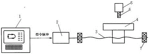
[0016] In order to make the object, technical solution and advantages of the present invention clearer, the present invention will be further described in detail below in conjunction with the accompanying drawings and embodiments. It should be understood that the specific embodiments described here are only used to explain the present invention, and are not intended to limit the present invention; the preferred embodiments of the present invention will be described in detail below in conjunction with the accompanying drawings, so that the advantages and features of the present invention can be more easily understood Those skilled in the art understand that, so that the protection scope of the present invention can be defined more clearly.

[0017] Such as figure 1 As shown, the present invention relates to an open-loop control CNC machine tool, including an MCU controller 1, a stepping motor 2, a screw mandrel 3, a machine tool table 4, a main shaft 5, a cutter 6 and a bearing...


PUM


Abstract

The invention relates to a control system of a numerical control machine tool. The control system comprises an MCU controller, a stepping motor, a lead screw, a machine tool working table, a main shaft, a tool and bearings. An instruction pulse output by the MCU controller is connected with the stepping motor. A drive shaft of the stepping motor is connected with and provided with the lead screw. The two ends of the lead screw are connected with and provided with the bearings. The lead screw and the machine tool working table are matched and connected with each other. A main shaft box is arranged above the machine tool working table. A feeding instruction signal output by the MCU controller controls and drives the motor through a pulse distributor. In addition, a speed detector and a position detector are arranged, the position detector is connected with a position comparator through a signal line, and the speed detector is connected with the speed controller through a signal line. Transmission error in a whole mechanical transmission chain from the motor to the machine tool working table is eliminated through feedback, and therefore the accurate position of the machine tool working table is obtained; the control system is convenient to control, simple in structure and low in price.

Description

technical field [0001] The invention relates to the technical field of control systems of numerical control machine tools, in particular to a control system of numerical control machine tools. Background technique [0002] CNC machine tools are high-tech machine tools with high machining accuracy and stable loading quality. They can perform multi-coordinate linkage and process parts with complex shapes. The existing CNC machining center has the following problems: (1) The positioning accuracy and rotation accuracy are low, and the dynamic rigidity is poor, so that the processed products have low dimensional accuracy, large shape and position errors, and poor surface accuracy, which cannot meet product quality requirements. Increase superfinishing and polishing process. (2) Insufficient rigidity of the machine tool produces vibration, making it impossible to perform high-speed and powerful grinding. (3) Friction and wear cause poor precision retention, many faults and sho...

Claims


Application Information

Patent Timeline
Patent Type & Authority Applications(China)
IPC IPC(8): B23Q15/00
CPCB23Q15/00
Inventor 曹华兴樊宗保吴维祥刘海玲韩宁
Owner WUHU RISHENG HEAVY DUTY MACHINE TOOLS
Learn More