Vehicle control method for solar electric vehicle
A solar electric vehicle, vehicle control technology, applied in electric vehicles, electric vehicle charging technology, electrical devices, etc., can solve problems such as complex control systems
- Summary
- Abstract
- Description
- Claims
- Application Information
AI Technical Summary
Problems solved by technology
Method used
Image
Examples
Embodiment 1
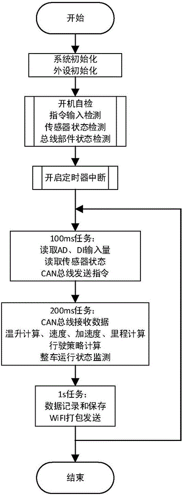
[0028] This embodiment provides a vehicle control method for a solar electric vehicle, such as figure 1 shown, including:
[0029] S1. System initialization, set the initial value of all peripherals, including clock, timer, digital input / output, analog-to-digital conversion, RS485 bus, CAN bus, WiFi communication;
[0030] CAN bus to realize communication with battery management system (BMS), motor controller, and solar cell peak power tracker (MPPT), with a baud rate of 125Kbps. The specific agreement is formulated according to the internal agreement of each component.
[0031] CAN bus and BMS realize two-way communication, read battery pack temperature, voltage, SOC, current and other data, and send battery pack output relay control signals. According to the highest single-cell battery voltage, the lowest single-cell single-cell voltage, and the highest single-group temperature signal control, if any quantity exceeds the threshold (that is, reaches the state of over-discha...
Embodiment 2
[0055] This embodiment provides a vehicle control method for a solar electric vehicle. The difference from Embodiment 1 is that the vehicle control method of this embodiment adds a redundant design to control the motor controller in a voltage mode, that is, when a CAN bus failure is detected, an analog signal is output to the motor controller to ensure that the motor controller The car continues to run stably.
[0056] Specifically, according to the control of the gear switch, accelerator and brake signals, 4 DA signals are output, of which 2 accelerator signals are the same and 2 brake signals are the same. When the input signal of the brake sensor is not zero, regardless of the state of the accelerator input signal at this time, the accelerator output signal is forced to be zero.
PUM
 Abstract
Description
Claims
Application Information
 - R&D
- Intellectual Property
- Life Sciences
- Materials
- Tech Scout
- Unparalleled Data Quality
- Higher Quality Content
- 60% Fewer Hallucinations
Browse by: Latest US Patents, China's latest patents, Technical Efficacy Thesaurus, Application Domain, Technology Topic, Popular Technical Reports.
© 2025 PatSnap. All rights reserved.Legal|Privacy policy|Modern Slavery Act Transparency Statement|Sitemap|About US| Contact US: help@patsnap.com

