Soap recycling device

A soap and crushing device technology, applied in the field of machinery, can solve the problems of unusable, waste of materials, inconvenient control of soap, etc., and achieve the effect of convenient use, high efficiency and exquisite structure

Inactive Publication Date: 2015-11-18
韦江华
View PDF3 Cites 2 Cited by
  • Summary
  • Abstract
  • Description
  • Claims
  • Application Information

AI Technical Summary

Problems solved by technology

[0006] Yet in the process of daily use, because soap is block, can consume gradually and become small block after long-term use, and the soap of small block is not easy to control, sometimes c

Method used


Image

  • Soap recycling device

Examples


Embodiment 1

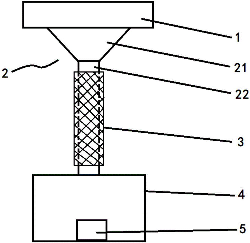
[0024] Such as figure 1 As shown, the present invention provides a soap recycling device, comprising a crushing device 1, a melting vessel 2, a heating screen 3, a base support 4 and a molding die 5, the crushing device 1 is located above the melting vessel 2, and the The lower surface of the crushing device 1 is in close contact with the upper surface of the melting vessel 2, the crushing device 1 has a material inlet and a material outlet, the melting vessel 2 has a funnel-shaped structure, and the melting vessel 2 includes a funnel cavity 21 and funnel neck 22, the lower end surface of the funnel cavity 21 is seamlessly connected with the upper end surface of the funnel neck 22, the upper end surface of the funnel cavity 21 is the inlet, the lower end surface of the funnel neck 22 is the outlet, and the pulverized The material inlet of the device 1 falls into the plane where the inlet of the funnel cavity 21 is located, the heating wire mesh 3 is set around the funnel neck ...

Embodiment 2

[0032] Such as figure 1 As shown, the present invention provides a soap recycling device, comprising a crushing device 1, a melting vessel 2, a heating screen 3, a base support 4 and a molding die 5, the crushing device 1 is located above the melting vessel 2, and the The lower surface of the crushing device 1 is in close contact with the upper surface of the melting vessel 2, the crushing device 1 has a material inlet and a material outlet, the melting vessel 2 has a funnel-shaped structure, and the melting vessel 2 includes a funnel cavity 21 and funnel neck 22, the lower end surface of the funnel cavity 21 is seamlessly connected with the upper end surface of the funnel neck 22, the upper end surface of the funnel cavity 21 is the inlet, the lower end surface of the funnel neck 22 is the outlet, and the pulverized The material inlet of the device 1 falls into the plane where the inlet of the funnel cavity 21 is located, the heating wire mesh 3 is set around the funnel neck ...


PUM


Abstract

The invention relates to the mechanical field and discloses a soap recycling device. The soap recycling device comprises a smashing device, a melting vessel, a heating screen, a base bracket and a molding die, wherein the smashing device is positioned above the melting vessel; the lower surface of the smashing device is tightly adhered to the upper surface of the melting vessel; the smashing device is provided with a feed inlet and a feed outlet; the melting vessel is in a funnel-shaped structure and comprises a funnel cavity and a funnel neck; the lower end face of the funnel cavity is seamlessly connected with the upper end face of the funnel neck; the upper end face of the funnel cavity is a lead inlet while the lower end face of the funnel neck is a lead outlet; the feed inlet of the smashing device falls into a plane of the lead outlet of the funnel cavity; the heating screen is arranged around the funnel neck; the base bracket is positioned below the melting vessel; the molding die is placed in the base bracket; the molding die is placed right below the lead outlet of the funnel neck. The soap recycling device disclosed by the invention can be used for smashing, melting and secondarily molding small block soaps to avoid material waste. The device is delicate in structure, convenient to use, comprehensive in function and convenient to operate.

Description

technical field [0001] The invention relates to the field of machinery, in particular to a soap recycling device. Background technique [0002] Soap is the general term for metal salts of fatty acids. The carbon number of fatty acids in daily-use soaps is generally 10-18. The metals are mainly alkali metals such as sodium or potassium, and ammonia and some organic bases such as ethanolamine and triethanolamine are also used for special purposes. Soapy. Soap includes laundry soap, toilet soap, metal soap, liquid soap, and related products fatty acid, hardened oil, glycerin, etc. [0003] In China's washing products, soap has a certain market demand. In daily life, people wash their faces and bathe with soap. In China with a large population, the demand for soap and soap is still very large. In the past 10 years, China's synthetic detergent It is still increasing at an annual rate of 8%. Therefore, China's detergent products, especially various synthetic detergent products,...

Claims


Application Information

Patent Timeline
IPC IPC(8): C11D13/30
Inventor 韦江华
Owner 韦江华
Why Eureka
Try Eureka