Eureka AIR delivers breakthrough ideas for toughest innovation challenges, trusted by R&D personnel around the world.

High-efficiency and energy-saving vertical sintering machine

A high-efficiency energy-saving, sintering machine technology, applied in the direction of dryers, furnace types, furnaces, etc., can solve the problems of low ore pre-reduction rate, continuous ignition of gas, difficult collection and treatment of smoke and dust, etc., to achieve good pre-return effect and equipment The effect of simple structure and high pre-reduction rate

Active Publication Date: 2017-03-15
钦州西北冶金设备有限公司
View PDF8 Cites 0 Cited by
  • Summary
  • Abstract
  • Description
  • Claims
  • Application Information

AI Technical Summary

Problems solved by technology

[0005] 1. The gas needs to be ignited continuously
[0006] 2. Large heat consumption
[0007] 3. The equipment is huge and the investment cost is high
[0009] 5. Low pre-reduction rate of ore
[0010] 6. The smoke and dust are difficult to collect and process, causing great pollution to the environment

Method used


Image

  • High-efficiency and energy-saving vertical sintering machine
  • High-efficiency and energy-saving vertical sintering machine

Examples


Embodiment Construction

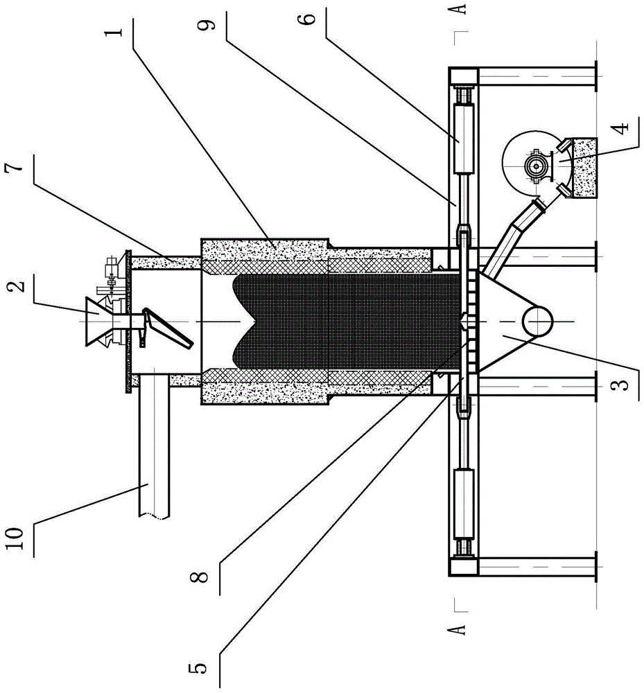
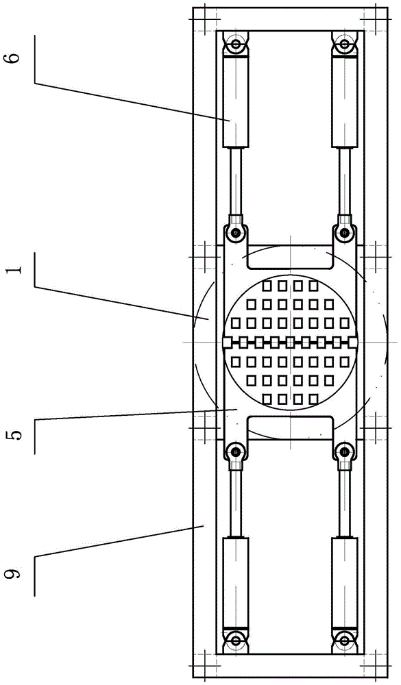
[0026] The technical solutions of the present invention will be further described below in conjunction with the embodiments shown in the accompanying drawings.

[0027] The high-efficiency energy-saving vertical sintering machine of the present invention, its main body is a furnace body 1 with a vertical structure, the inner wall of the furnace body is built with refractory bricks to form a furnace, and an igniter is arranged in the furnace, and the furnace body 1 is supported by a furnace frame 9 On site, a furnace cover 7 is built on the top of the furnace body 1 (i.e., a feed port), the top of the furnace cover 7 is placed with a feed bin 2, and the smoke outlet on the side of the furnace cover 7 is connected to a flue 10, and the flue 10 communicates with the dust collector, the unloading bin 3 is arranged below the lower opening (i.e., the discharge port) of the furnace body 1 in the furnace frame 9 and communicates with the discharge port, and the discharge port of the fu...


PUM


Abstract

The invention discloses an efficient and energy-saving vertical type sintering machine. The sintering machine comprises a furnace body. The upper opening of the furnace body is a feeding inlet. A feeding bin is arranged at the feeding inlet through a furnace cover. A dust remover is communicated with the furnace cover through a pipeline. The lower opening of the furnace body is a discharging outlet. The discharging outlet is provided with a grill plate. A discharging bin is arranged at the discharging outlet of the furnace body. An air blower is communicated with the discharging bin through a pipeline. A left discharging plate and a right discharging plate are arranged on the two sides, above the grill plate, of the furnace body in symmetry. A left notch and a right notch which correspond to the left discharging plate and the right discharging plate respectively are formed in the furnace body and allowing the left discharging plate and the right discharging plate to come in and go out. The front end of the left discharging plate and the front end of the right discharging plate are provided with cutting edges. The rear end of the left discharging plate and the rear end of the right discharging plate are connected to piston rods arranged on a left discharging oil cylinder and a right discharging oil cylinder respectively, and the piston rods stretch out and retract synchronously. The sintering machine can achieve continuous sintering by being ignited once and the sintering machine is long in sintering time, even in heating, good in forming of a sintered product, low in powder ratio, good in pre-reduction effect of ore, low in energy consumption, clean and environmentally friendly.

Description

technical field [0001] The invention relates to sintering equipment, in particular to a high-efficiency and energy-saving vertical sintering machine. Background technique [0002] Sintering is to mix iron-containing raw materials, fuels, solvents, etc. together in proportion, after mixing and granulating, add water to moisten, spread on the sintering equipment, ignite and sinter from top to bottom, and start to draw air from the bottom of the sintering machine at the same time , the fuel in the mixed ore is burned from top to bottom, and the concentrate powder and rich ore powder with different components and particle sizes are sintered into blocks, and the sulfur, phosphorus and other harmful impurities contained in the ore are partially eliminated, and the mixture after combustion It becomes sintered ore with high iron content and is supplied to blast furnace. [0003] Most of the currently used sintering machines are ring sintering machines and belt sintering machines. ...

Claims


Application Information

Patent Timeline
Patent Type & Authority Patents(China)
IPC IPC(8): F27B21/10F26B21/12F26B21/08
Inventor 吴月明
Owner 钦州西北冶金设备有限公司
Why Eureka
Eureka Blog
Learn More