CAN-bus rotating speed sensor and data processing method based on CAN bus
A CAN bus and speed sensor technology, applied in the field of vehicles, can solve problems such as inability to guarantee accurate and fast feedback, damage to vehicle circuit systems, and poor information quality, so as to improve portability and practicability, meet actual work needs, and ensure stability sexual effect
- Summary
- Abstract
- Description
- Claims
- Application Information
AI Technical Summary
Problems solved by technology
Method used
Image
Examples
Embodiment 1
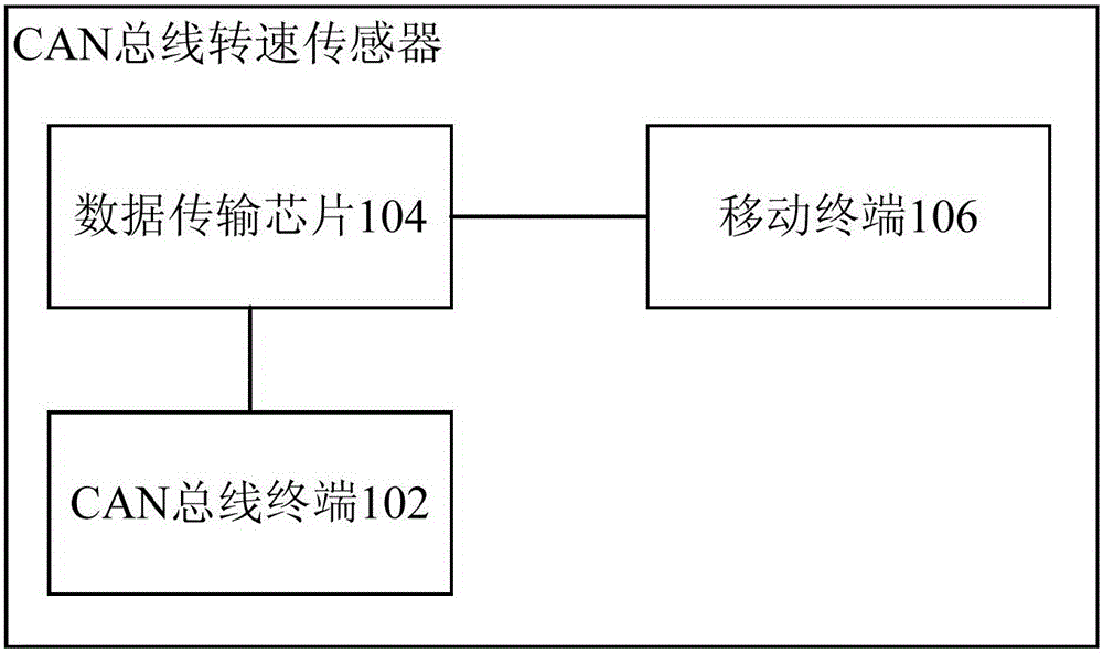
[0037] refer to figure 1 , shows a schematic structural diagram of a CAN bus speed sensor in Embodiment 1 of the present invention. In this embodiment, the CAN bus speed sensor may include:
[0038] The CAN bus terminal 102 is used to collect parameter information of the vehicle and send a message carrying the parameter information.
[0039] CAN bus, ControllerAreaNetwork, controller area network bus, is a serial communication protocol bus for real-time applications, which can use twisted-pair wires to transmit signals. In this embodiment, the parameter information of the vehicle can be collected based on the CAN bus through the CAN bus terminal 102. For example, the CAN bus terminal can receive the vehicle body bus signal based on the standard protocol of the CAN bus, wherein the vehicle body bus signal carries the Various parameter information, the parameter information may include but not limited to: vehicle speed signal, wheel speed signal, vehicle body acceleration sign...
Embodiment 3
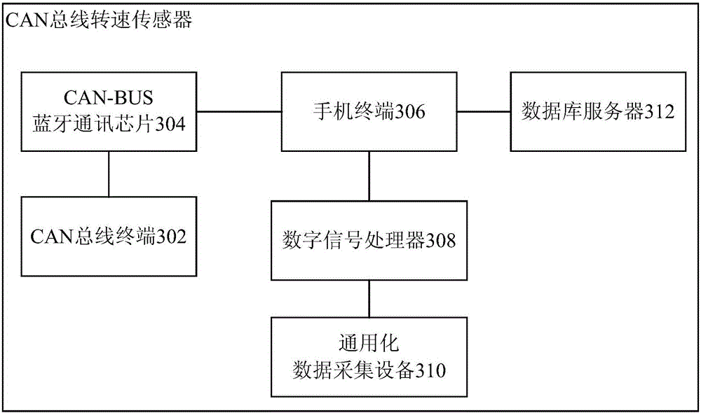
[0067] Based on the above-mentioned embodiments, this embodiment takes the actual application of the CAN bus speed sensor in vehicles as an example to describe the structure of the CAN bus speed sensor in detail. If there is no contradiction, the CAN bus speed described in this embodiment The sensor can be combined with the CAN bus speed sensor described in the above embodiments. The structure of the CAN bus speed sensor described in this embodiment will be specifically described below.
[0068] refer to image 3 , shows a schematic structural diagram of a CAN bus speed sensor in Embodiment 3 of the present invention. In this embodiment, the CAN bus speed sensor may include: a CAN bus terminal 302, a data transmission chip connected to the vehicle body through the vehicle body OBD II interface, a mobile terminal, a digital signal processor 308, a generalized data acquisition device 310 and a database server 312. Wherein, in this embodiment, the data transmission chip may sp...
Embodiment 4
[0082] Based on the same inventive concept as the above device embodiment. refer to Figure 4 , shows a flow chart of steps of a CAN bus-based data processing method in Embodiment 4 of the present invention. In this embodiment, the CAN bus-based data processing method may include:
[0083] Step 402, obtaining a message carrying parameter information of the vehicle from the CAN bus terminal.
[0084] Step 404, sending the message to the mobile terminal through the data transmission chip.
[0085] In step 406, the mobile terminal parses the message to obtain first data information for indicating vehicle speed and / or engine speed.
[0086] Step 408, loading and displaying the first data information in the terminal interface of the mobile terminal.
[0087] To sum up, according to the data processing method based on the CAN bus speed sensor described in this embodiment, the CAN bus terminal can directly collect the original parameter information from the vehicle without any si...
PUM
 Abstract
Description
Claims
Application Information
 - R&D
- Intellectual Property
- Life Sciences
- Materials
- Tech Scout
- Unparalleled Data Quality
- Higher Quality Content
- 60% Fewer Hallucinations
Browse by: Latest US Patents, China's latest patents, Technical Efficacy Thesaurus, Application Domain, Technology Topic, Popular Technical Reports.
© 2025 PatSnap. All rights reserved.Legal|Privacy policy|Modern Slavery Act Transparency Statement|Sitemap|About US| Contact US: help@patsnap.com


