
Composite high voltage insulator

A high-voltage insulator and composite technology, applied in the direction of transformer/inductor coil/winding/connection, etc., can solve the problems of heavy transformer, large size and weight, and achieve the effect of simple structure, reduced volume and guaranteed contact

Active Publication Date: 2017-01-18
无锡希恩电气有限公司
View PDF12 Cites 0 Cited by
  • Summary
  • Abstract
  • Description
  • Claims
  • Application Information

AI Technical Summary

Problems solved by technology

[0002] At present, high-voltage transformers with oil tank structures are widely used, and the voltage of high-voltage transformers is getting higher and higher. The withstand voltage requirements for high-voltage insulators are also increasing. Traditional ceramic insulators must be very large in size and meet the corresponding withstand voltage requirements. weight, making the transformer very bulky

Method used


Image

  • Composite high voltage insulator

Examples


Embodiment Construction

[0012] Below the present invention will be further described in conjunction with the embodiment in the accompanying drawing:

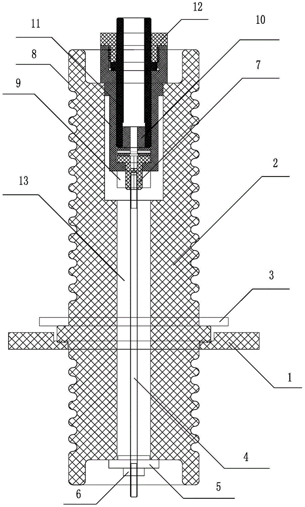
[0013] like figure 1 As shown, the present invention mainly includes an insulating flange 1, a cylinder 2, an insulating pressure plate 3, a conductive screw 4, a conductive seat 7, a conductive joint 10 and an insulating sheath 11, and the outer ring of the cylinder 2 is fixedly connected to the insulating flange 1 and the insulating The pressing plate 3 realizes the insulation and fixing of the column body 2 through the insulating flange 1 and the insulating pressing plate 3 .

[0014] The lower part of the central inner hole of the cylinder 2 is provided with a conductive screw 4 , and the lower end of the conductive screw 4 protrudes from the cylinder 2 and is connected to an insulating backing plate 5 .

[0015] There is a certain gap 13 between the conductive screw 4 and the central inner hole wall of the cylinder 2, and the gap 13 is filled wit...


PUM


Abstract

The invention relates to an insulator, in particular to a compound high-pressure insulator, and belongs to the technical field of insulators. The compound high-pressure insulator comprises an insulating flange, a column body, an insulating press plate, a conductive lever, a conductive seat, a conductive connector and an insulating sheath; the conductive lever is arranged on the lower portion of a central inner hole of the column body, and the lower end of the conductive lever stretches out of the column body and is connected with an insulating padding plate; the upper portion of the central inner hole of the column body is provided with a conductive chamber, the conductive connector is arranged in the conductive chamber, the lower end of the conductive connector is connected with the upper end of the conductive lever through the conductive seat, and the upper end of the conductive connector is connected with the insulating sheath. According to the compound high-pressure insulator, the creep distance is increased by arranging the insulating flange, the structure of an insulating casing pipe and the structure of arranging a parachute cluster, the height and size of the insulator can be reduced, and meanwhile the pressure-resistance requirement is met; the adopted conductive connector is deep buried in the column body, therefore, the creep distance can be increased, and the purpose of improving the pressure resistance is achieved.

Description

technical field [0001] The invention relates to an insulator, in particular to a composite high-voltage insulator, which belongs to the technical field of insulators. Background technique [0002] At present, high-voltage transformers with oil tank structures are widely used, and the voltage of high-voltage transformers is getting higher and higher. The withstand voltage requirements for high-voltage insulators are also increasing. Traditional ceramic insulators must be very large in size and meet the corresponding withstand voltage requirements. The weight makes the transformer very bulky. Contents of the invention [0003] The purpose of the present invention is to overcome the above disadvantages, thereby providing a composite high-voltage insulator, which has small volume, good voltage resistance performance, and can be customized according to user needs. [0004] According to the technical solution provided by the present invention, the composite high-voltage insulat...

Claims


Application Information

Patent Timeline
Patent Type & Authority Patents(China)
IPC IPC(8): H01F27/32H01F27/29
Inventor 钱明徐惠丰周晓东
Owner 无锡希恩电气有限公司
Learn More