DC contactor packaging structure

A DC contactor and packaging structure technology, applied in the direction of relays, electromagnetic relays, electromagnetic relay details, etc., can solve the problems of increasing installation space, many processes, increasing production costs, etc., to reduce production costs, change installation methods, reduce The effect of product volume

Inactive Publication Date: 2015-11-18
KUNSHAN GUOLI VACUUM ELECTRIC
View PDF8 Cites 6 Cited by
  • Summary
  • Abstract
  • Description
  • Claims
  • Application Information

AI Technical Summary

Problems solved by technology

Since the bottom of the plastic shell needs to be provided with mounting holes, a part of the bottom of the plastic shell needs to be extended outward to make the mounting holes, which not only increases the manufacturing cost, but also increases the volume of the DC contactor and increases the installation space; at the same time, the plastic shell installation Finally, potting glue is required for fixing, and there are relatively many procedures, low manufacturing efficiency, and high cost; in addition, because the connecting cables 17 on the two screw rods of the DC contactor are located on the upper side, and the mounting plate is located at the bottom of the DC contactor. side, so the installation board and the circuit board need to be installed separately, and are separated from the opposite sides of the DC contactor, which further increases the installation space and installation process

Method used


Image

  • DC contactor packaging structure
  • DC contactor packaging structure
  • DC contactor packaging structure

Examples


Embodiment Construction

[0022] A preferred embodiment of the present invention will be described in detail below in conjunction with the accompanying drawings. However, the scope of protection of the present invention is not limited to the following examples, that is, any simple equivalent changes and modifications made based on the patent scope of the present invention and the content of the description are still within the scope of the patent of the present invention.

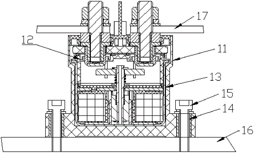
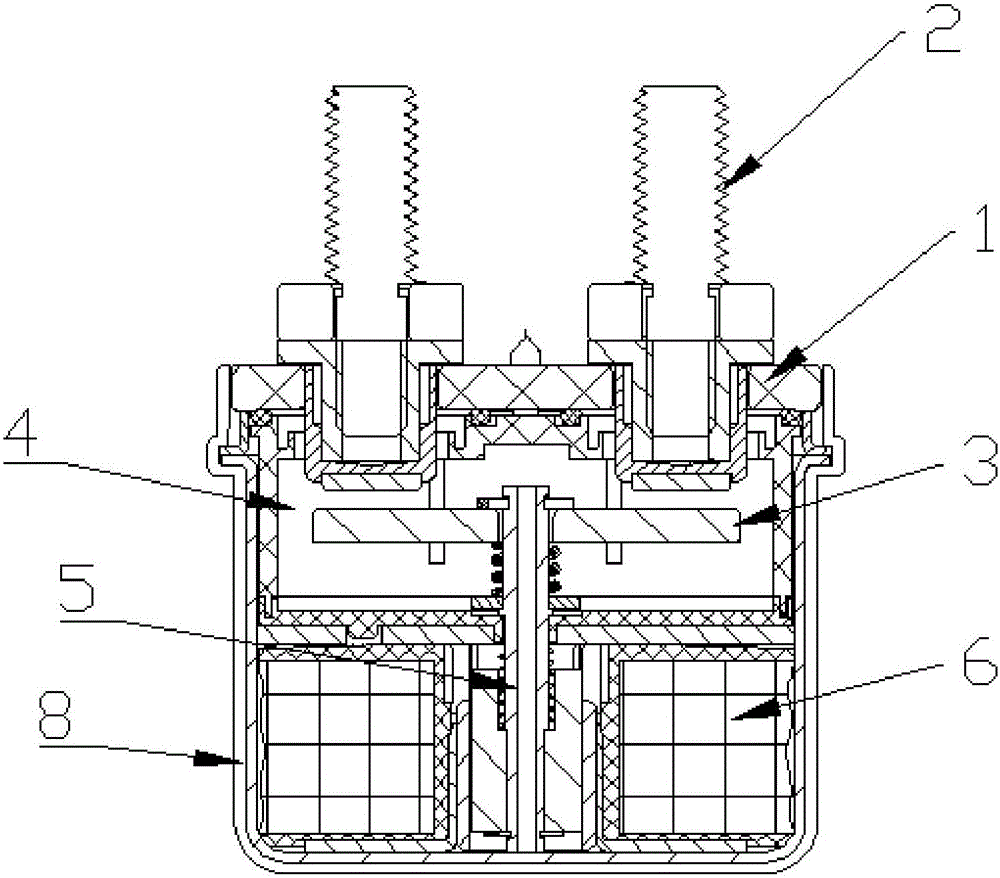
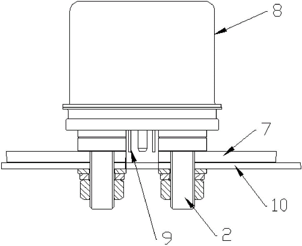
[0023] A DC contactor packaging structure, such as figure 2 As shown, it includes a DC contactor body 1, which is equipped with two screw rods 2 for forming static contacts, a moving contact piece 3 for forming moving contacts, an arc extinguishing chamber 4 for arc extinguishing, and In terms of the transmission part 5 and the coil structure 6 that drive the moving contact, the outer ends of the two screws protrude from the upper side of the DC contactor body, and the two screws, the moving contact piece and the coil are respectiv...


PUM


Abstract

The invention discloses a DC contactor packaging structure, which comprises a DC contactor body. The DC contactor body is internally provided with two screw rods for forming static contacts, a moving contact sheet for forming a moving contact, an arc extinguishing chamber for arc extinguishing, a transmission part for driving the moving contact to move and a coil structure, wherein outer ends of the two screw rods extend out of the upper side surface of the DC contactor body; the two screw rods, the moving contact sheet and the coil introduce connection lines outwardly on the upper side surface of the DC contactor body; the lower side surface and the outer side surface of the DC contactor body are fixedly sleeved with a metal casing; and the metal casing and the DC contactor contact parts are firmly connected and sealed. The DC contactor packaging structure uses a light and thin metal casing to replace a mounting casing and a pouring sealant, parts are simplified, the product size is reduced, the manufacturing cost is reduced, the traditional mounting mode is changed, mounting is more convenient and quicker, and the occupied space is small.

Description

technical field [0001] The invention relates to an electronic component for automatically controlling electronic discontinuity, in particular to a packaging structure of a DC contactor. Background technique [0002] DC contactor is mainly composed of arc extinguishing chamber, transmission part, coil, etc. Its packaging methods are divided into non-sealed type, epoxy glue sealed type and ceramic metallized type. This type of DC contactor has the ability to switch DC loads under high voltage. Ability. At present, the existing DC contactors on the market, such as figure 1 As shown, the plastic shell 11 is used to cover the DC contactor body 12, and then the potting glue 13 is fixed between the plastic shell and the DC contactor body to complete the package. For installation, a mounting hole 14 is provided at the bottom of the plastic shell. Mounting screws 15 are installed in the mounting holes to fix the plastic shell to the user's mounting plate 16 . Since the bottom of t...

Claims


Application Information

Patent Timeline
Patent Type & Authority Applications(China)
IPC IPC(8): H01H50/04H01H50/02
CPCH01H50/045H01H50/02
Inventor 覃奀垚黄浩程庆勇
Owner KUNSHAN GUOLI VACUUM ELECTRIC
Why Eureka
Try Eureka