Anti-frost and anti-freezing apparatus
An antifreeze device and anti-frost technology, applied in horticulture, application, botanical equipment and methods, etc., can solve the problems of promoting frost damage and rising fuel costs
- Summary
- Abstract
- Description
- Claims
- Application Information
AI Technical Summary
Problems solved by technology
Method used
Image

Examples
no. 1 approach
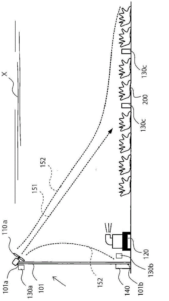
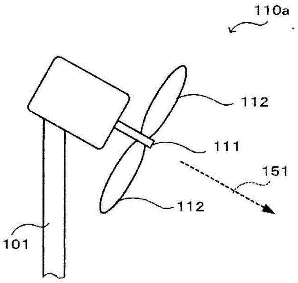
[0041] figure 1is a view showing the structure of the frost and freeze protection device 1 according to the first embodiment of the present invention. The anti-frost and anti-freezing device 1 utilizes a plurality of columns 101 (columns, telescopic columns), 102 ... (assuming that the columns 101 are erected in the field A, and will be separately described below if there are many), and one of the upper parts 101a of the column 101 One or more first fans 110a (elevated fans), one or more heaters 120 arranged in the lower part 101b of the column 101 or suitable places in the field A and the first sensors arranged near the column 101 and in the upper part 101a 130a (first temperature sensor) and the second sensor 130b (second temperature sensor) arranged in the lower part 101b, one or more for detecting the temperature near the crops 200 in the field A (the temperature of the leaves of the crops 200) The third sensor 130c (third temperature sensor) is constituted.
[0042] Th...
no. 2 approach
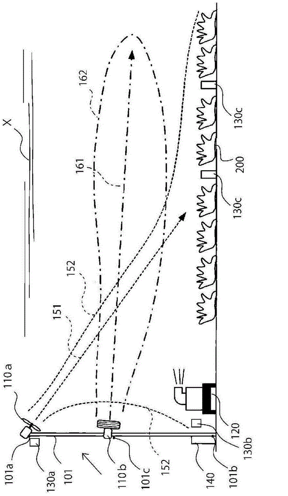
[0063] figure 2 is a view showing the structure of a frost and freeze protection device 1 according to a second embodiment of the present invention. The anti-frost and anti-freezing device 1 utilizes a plurality of columns 101 erected in the field A, one or more first fans 101a (fans) arranged on the top 101a of the columns 101, and one or more first fans 101a (fans) arranged on the middle part 101c of the columns 101. A second fan 110b (the fan in the middle) and one or more heaters 120 arranged in the lower part 101b of the column 101 or in a suitable place in the field A, and the control of the lower part 101b near the column 101 The sensor is composed of a first sensor 130a, a second sensor 130b, and one or more third sensors 130c for detecting the temperature near the crops 200 in the field A.
[0064] The composition of each structure is according to the above-mentioned first embodiment. In addition, in the second embodiment, the second fan 110b is basically installed...
no. 3 approach
[0074] exist Figure 4 and Figure 5 Among them, the first fan 110a (instead of the second fan 110b) is installed on the upper part 101a of the telescopic column 101. For example, the column 101 can be extended and contracted by the control of the controller. The first fan 110a moves up and down as the column 101 expands and contracts. Figure 4 It shows the state that the first fan 110a is at a high position, Figure 5 The state where the fan 110a is in the middle part 101c is shown. That is, the operation according to the second embodiment is performed with the first fan 101a replaced, so equipment saving and cost saving are realized.
[0075] Other variants of the second embodiment 1, 2
[0076] Figure 8 and Figure 9 are other modifications 1 and 2 showing the structure of the frost and freeze protection device 1 according to the second embodiment of the present invention.
[0077] exist Figure 8 In the anti-frost and anti-freeze device 1 of other modification 1...
PUM
 Abstract
Description
Claims
Application Information
 - R&D
- Intellectual Property
- Life Sciences
- Materials
- Tech Scout
- Unparalleled Data Quality
- Higher Quality Content
- 60% Fewer Hallucinations
Browse by: Latest US Patents, China's latest patents, Technical Efficacy Thesaurus, Application Domain, Technology Topic, Popular Technical Reports.
© 2025 PatSnap. All rights reserved.Legal|Privacy policy|Modern Slavery Act Transparency Statement|Sitemap|About US| Contact US: help@patsnap.com