Machining method for rim blank for spinning rim

A processing method and technology of spinning rims, applied to rims, transportation and packaging, vehicle parts, etc., can solve the problems of enhanced molding stability, increased production efficiency, and accelerated production tempo, achieving strong molding stability and high production efficiency , The effect of fast production tempo

Inactive Publication Date: 2015-11-25
ZHEJIANG JINGU CO LTD
View PDF6 Cites 4 Cited by
  • Summary
  • Abstract
  • Description
  • Claims
  • Application Information

AI Technical Summary

Problems solved by technology

However, there are still some areas for improvement: faster production tact, increased production efficiency, etc., and enhanced molding stability

Method used


Image

  • Machining method for rim blank for spinning rim

Examples


Embodiment

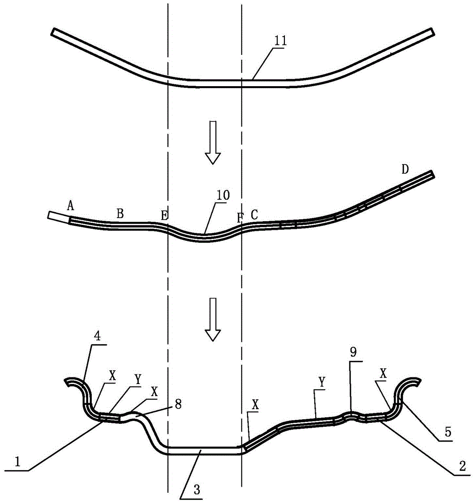
[0012] Embodiment: the present invention a kind of spinning wheel rim blank processing method, as attached figure 1 As shown, segmental spinning is carried out on the flaring rim blank 11 with a flat bottom in the middle and oblique extensions on both sides; first, the EF segment is rolled into a positioning protrusion 10, and the positioning protrusion 10 is used to position the workpiece ; Then spin the AB section for thinning, and then spin the CD section for thinning. While spinning, the workpiece width becomes wider, and the longest increased width is 40mm. Spinning forms the outer bead seat 1, the inner bead seat 2, the base 3, the outer rim 4, the inner rim 5, the outer convex peak 8, and the inner convex peak 9.

[0013] The thinning of the AB and CD sections is between 25% and 50%. Thinning refers to the ratio of the subtracted thickness to the original thickness.

[0014] The arching direction of the positioning protrusion 10 is opposite to the flaring direction of...


PUM


Abstract

The invention relates to a machining method for a rim blank for spinning rim. The machining method is used for conducting segmented spinning machining on the flaring rim blank, wherein the middle of the rim blank is a flat bottom, and the two sides of the rim blank extend obliquely. The method includes the steps that firstly, the EF segment is rolled to form positioning protrusions, and the positioning protrusions are used for positioning a workpiece; secondly, the AB segment is spun to be thinned; and thirdly, the CD segment is spun to be thinned, the width of the workpiece is widened while spinning is conducted, and the increased maximum width is 40 mm. By means of the manner, spinning force is smaller, energy is greatly reduced, and abrasion on a die is smaller; the molding quality can be effectively improved, and stability after forming is further enhanced; and in addition, the quality qualification rate is also increased, the production takt is faster, and the production efficiency is higher.

Description

technical field [0001] The invention relates to a processing technology for auto parts, in particular to a processing method for a rim blank for spinning rims. Background technique [0002] In order to solve the problems of heavy weight, high driving resistance and insufficient and easy deformation of the existing automobile rim, and to coordinate the strength and weight of the rim, the inventor proposed a method called "automotive rim and its spinning process" ( Publication No. CNl03448466A), which includes an outer bead seat, an inner bead seat, a bottom groove arranged between the inner bead seat and the outer bead seat, an outer rim connected to the end of the outer bead seat, a rim connected to the end of the inner bead seat The inner rim, the outer bead seat and the inner bead seat are respectively provided with an outer spinning area and an inner spinning area, and the outer spinning area extends from the connection position between the outer bead seat and the outer r...

Claims


Application Information

Patent Timeline
Patent Type & Authority Applications(China)
IPC IPC(8): B21D22/16B21D53/30
Inventor 李顺平孙锋峰盛枫谷进进汪冬冬
Owner ZHEJIANG JINGU CO LTD
Why Eureka
Try Eureka