Automatic bearing bush boring mill system

A bearing bush and boring machine technology, which is applied in the field of boring machines, can solve the problems of high cost, time-consuming and labor-intensive use, and reduced number of carcass uses

Active Publication Date: 2015-11-25
YANTAI DONGZE ELECTRICAL TECH CO LTD
View PDF7 Cites 7 Cited by
  • Summary
  • Abstract
  • Description
  • Claims
  • Application Information

AI Technical Summary

Problems solved by technology

[0002] At present, the fine boring mold of the bearing bush is generally an integral structure, and it needs to be aligned by its own boring before each use, resulting in reduced use times of the carcass, long construction period and high cost
At present, the temperature control of the hydraulic power head of the bearing pad boring machine is strictly controlled. After starting the machine, wait for the temperature of the spindle head to stabilize before processing. The warm-up time is too long. Precisely manufactured, according to the design requirements of high engine speed and friction resistance, the wall thickness of the upper end of the inner diameter surface of the bearing pad must be thinned by 0.03-0.05mm, and the thinning length is 5-12mm. The traditional process is to adjust the slight deformation of the upper end of the bottom mold of the bearing pad to thin, but the thinning length cannot be guaranteed
The current bearing bush boring machine is manually put in a piece of bearing bush, start the boring of the spindle head, stop the spindle head after completion, in order to avoid scratching the surface of the bearing bush, it is necessary to turn the boring tool to the direction away from the bearing bush, and take out the bearing bush, which is inconvenient to operate. At present, the bearing bush equipment is large. Partially rely on manual loading and unloading and wiping the bearing bush, which is time-consuming and laborious. At present, the use of the boring tool of the bearing bush boring machine is generally judged by observing the inner surface of the processed bearing bush to determine whether the boring tool needs to be replaced. There may be errors in the judgment, and it is easy to lack monitoring.

Method used


Image

  • Automatic bearing bush boring mill system
  • Automatic bearing bush boring mill system
  • Automatic bearing bush boring mill system

Examples


Embodiment Construction

[0029] The principles and features of the present invention are described below in conjunction with the accompanying drawings, and the examples given are only used to explain the present invention, and are not intended to limit the scope of the present invention.

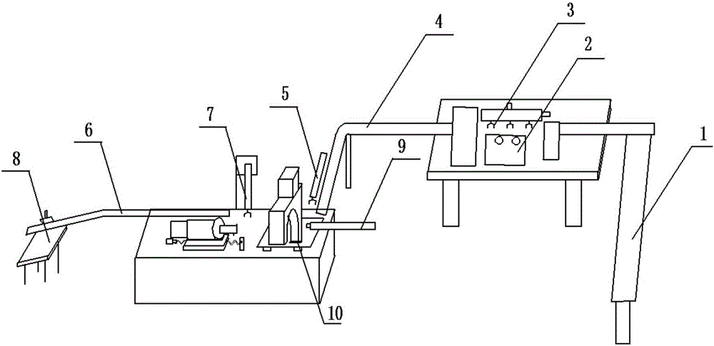
[0030] Such as figure 1 The automatic bearing bush boring machine system shown is characterized in that it includes a feeding conveyor belt 1, a cleaning machine 2, a cleaning manipulator 3, a processing conveyor belt 4, a feeding manipulator 5, a machine tool body, a feeding conveyor belt 6, a feeding manipulator 7, a storage Disk 8, sensor, PLC control module and alarm module;

[0031] The feeding conveyor belt 1 is used to transport the bearing bush to the washing machine 2;

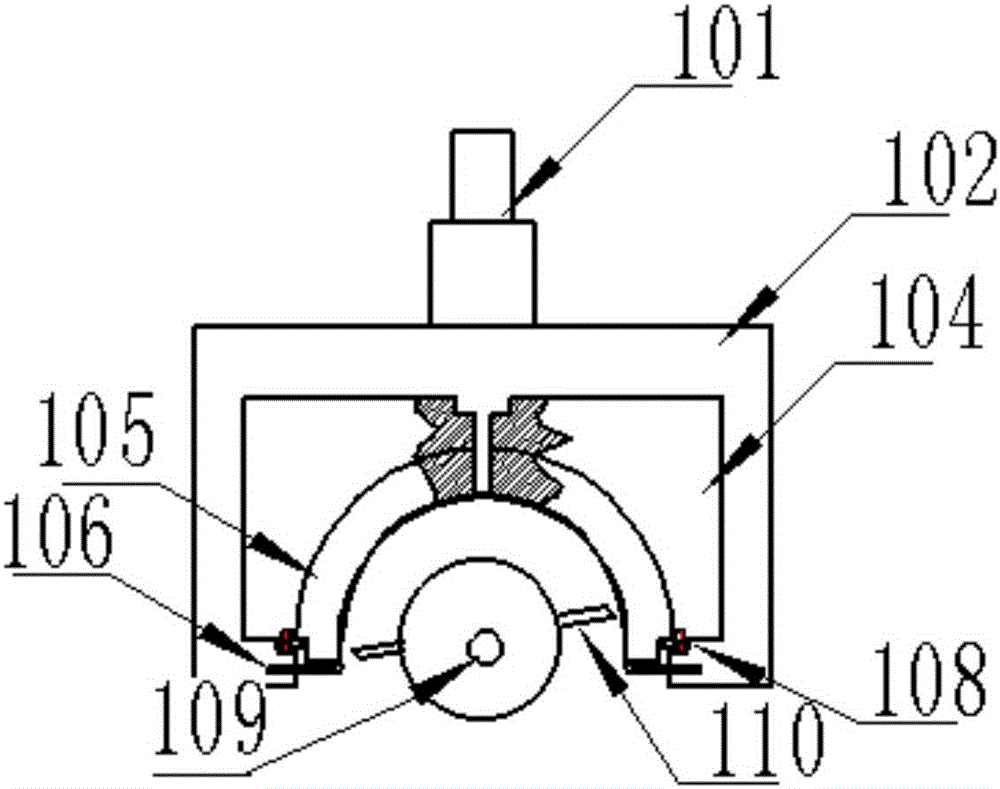
[0032] Specifically, such as Figure 5 As shown, after the bearing pad is transferred to the washing machine 2, it enters the first tile tire 204, and the cleaning manipulator 3 places the bearing pad on the polishing wheel 207. The polis...


PUM


Abstract

The invention relates to an automatic bearing bush boring mill system, and belongs to the field of boring mills. The automatic bearing bush boring mill system particularly comprises a feeding conveying belt, a cleaning machine, a cleaning manipulator, a machining conveying belt, a feeding manipulator, a mill body, a discharging conveying belt, a discharging manipulator, a storage disk, a sensor, a programmable logic controller (PLC) control module and an alarm module. The feeding conveying belt is used for conveying bearing bushes to the cleaning machine. After the cleaning machine cleans the bearing bushes, the cleaning manipulator places the bearing bushes onto the machining conveying belt. The machining conveying belt conveys the bearing bushes to the feeding device. The feeding manipulator is used for putting the bearing bushes on the machining conveying belt on the mill body. The mill body comprises a pushing air cylinder and a die fixing device. A blank die can be taken out and replaced conveniently and rapidly. After machining, a servo motor controls the blank die to move upwards. A second time of boring of the bearing bushes is not needed. A boring cutter can retreat in any position to prepare for the next cycle.

Description

technical field [0001] The invention relates to the field of boring machines, in particular to an automatic bush boring machine system. Background technique [0002] At present, the fine boring mold of the bearing bush is generally an integral structure, and needs to be aligned by self-boring before each use, resulting in reduced use times of the carcass, long construction period and high cost. At present, the temperature control of the hydraulic power head of the bearing pad boring machine is strictly controlled. After starting the machine, wait for the temperature of the spindle head to stabilize before processing. The warm-up time is too long. Precisely manufactured, according to the design requirements of high engine speed and friction resistance, the wall thickness of the upper end of the inner diameter surface of the bearing pad must be thinned by 0.03-0.05mm, and the thinning length is 5-12mm. The traditional process is to adjust the slight deformation of the upper e...

Claims


Application Information

Patent Timeline
Patent Type & Authority Applications(China)
IPC IPC(8): B23B41/00B23B47/00
CPCB23B41/00B23B47/00
Inventor 林书海林萌
Owner YANTAI DONGZE ELECTRICAL TECH CO LTD
Why Eureka
Try Eureka