
Patsnap Eureka
For R&D, Patsnap Eureka makes reading and utilizing patents & technical documents easy.
Patsnap Eureka AIR
Designed for self-driven R&D workflows. Generate viable solutions, solve complex R&D challenges, empower your innovation with AI.

Patsnap Eureka Materials
Designed for material experts only. Revolutionize your material R&D, from search, analyze, to developing new materials.

TechResearch
Generate reliable direction feasibility study reports for your R&D in just a few steps.

TechSeek
Discover and master advanced knowledge NOW. Basics, ideas, possibilities, all at once.

TechMind
As an expert in R&D Theories, TechMind can generates customized viable solutions instantly.

TechRisk
Analyze your overall solution with one click, know your potential R&D risks in advance.

TechMonitor
Get weekly tech updates, stay abreast of the latest tech innovations and key insights.
Laser welding method
A laser welding, laser beam technology, applied in laser welding equipment, welding equipment, metal processing equipment and other directions, can solve the problem of welding part Y that cannot obtain a stable shape, etc.
- Summary
- Abstract
- Description
- Claims
- Application Information
AI Technical Summary
Problems solved by technology
Method used
Image

Examples
no. 1 approach
[0050] 1. About device configuration
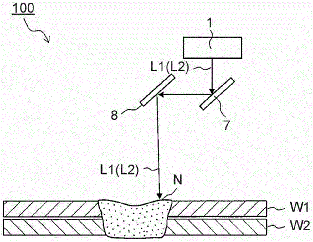
[0051] FIG. 1 is a schematic diagram of one example of a welding apparatus for performing laser welding methods according to first to third embodiments of the present invention. Figure 1A is a view along the transverse direction of the fusion state of the nugget, and Figure 1B is a frontal view of the welded state of the nugget.
[0052] The welding apparatus shown in FIG. 1 includes a laser beam irradiation section 1 as a main component. The laser beam irradiation section 1 is a device that supplies laser beams (first laser beams or second laser beams) L1, L2 for welding and projects the selected laser beams onto two metal workpieces W1, W2, which The metal workpieces W1, W2 are stacked or arranged with a slight gap therebetween.
[0053] In the present embodiment and the second embodiment, only the welding laser beam (first laser beam L1 ) for forming each nugget N constituting the welding portion is used. In the third embodiment,...
no. 2 approach
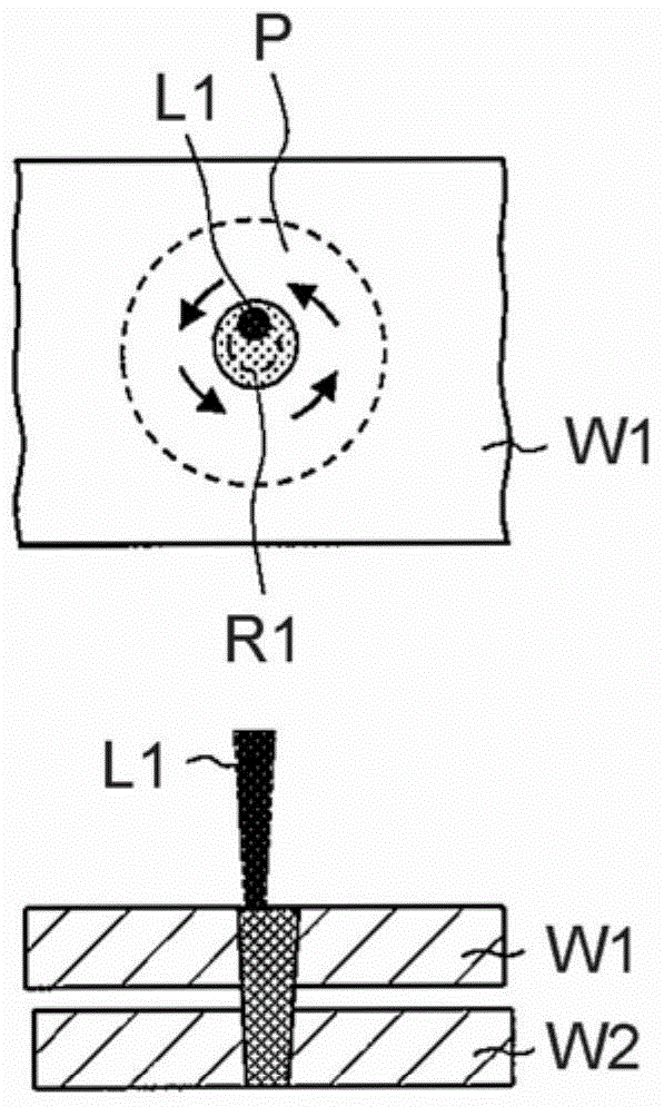
[0087] 4 includes views for explaining a laser welding method according to a second embodiment, in which, Figure 4A showing a virtual closed curve on the workpiece and an irradiation area of the first laser beam before the first laser beam is projected onto the workpiece, Figure 4B shows the relationship between each of the irradiated areas and the total heat input, and Figure 4C Shows the state of the nugget.
[0088] This embodiment differs from the first embodiment in that the first laser beam L1 is Figure 4A The images shown are projected onto the shot regions P1 to P6 in order, thereby forming nuggets N1 to N6 in order.
[0089] In this embodiment, if Figure 4A As shown in , the center of a circle passing through the irradiation area P1 to the irradiation area P6 (the nugget N1 to the nugget N6 ) is determined, and the outer peripheral diameter of the closed curve D corresponding to the circumference is set. Next, the first laser beam L1 follows the Figure 2A...
PUM
 Abstract
Description
Claims
Application Information
 - R&D Engineer
- R&D Manager
- IP Professional
- Industry Leading Data Capabilities
- Powerful AI technology
- Patent DNA Extraction
Browse by: Latest US Patents, China's latest patents, Technical Efficacy Thesaurus, Application Domain, Technology Topic, Popular Technical Reports.
© 2024 PatSnap. All rights reserved.Legal|Privacy policy|Modern Slavery Act Transparency Statement|Sitemap|About US| Contact US: help@patsnap.com