Machining process method for complex support parts

A process method and machining technology, which are applied in the field of machining process of complex bearing parts to achieve the effect of improving the machining efficiency and ensuring the qualified rate

Active Publication Date: 2015-11-25
HARBIN
View PDF5 Cites 7 Cited by
  • Summary
  • Abstract
  • Description
  • Claims
  • Application Information

AI Technical Summary

Problems solved by technology

[0008] The technical problem to be solved by the present invention: various

Method used


Image

  • Machining process method for complex support parts
  • Machining process method for complex support parts
  • Machining process method for complex support parts

Examples


Example Embodiment

[0026] The installation and working mode of the present invention will be described below in conjunction with the accompanying drawings of the specification.

[0027] A mechanical processing method for complex bearing parts, the specific steps are as follows:

[0028] 1 process: milling

[0029] Milling hexagon: blank size: length is 436 width is 328 thickness: 95

[0030] 2 process: fitter

[0031] Deburring

[0032] 3 process: machining center
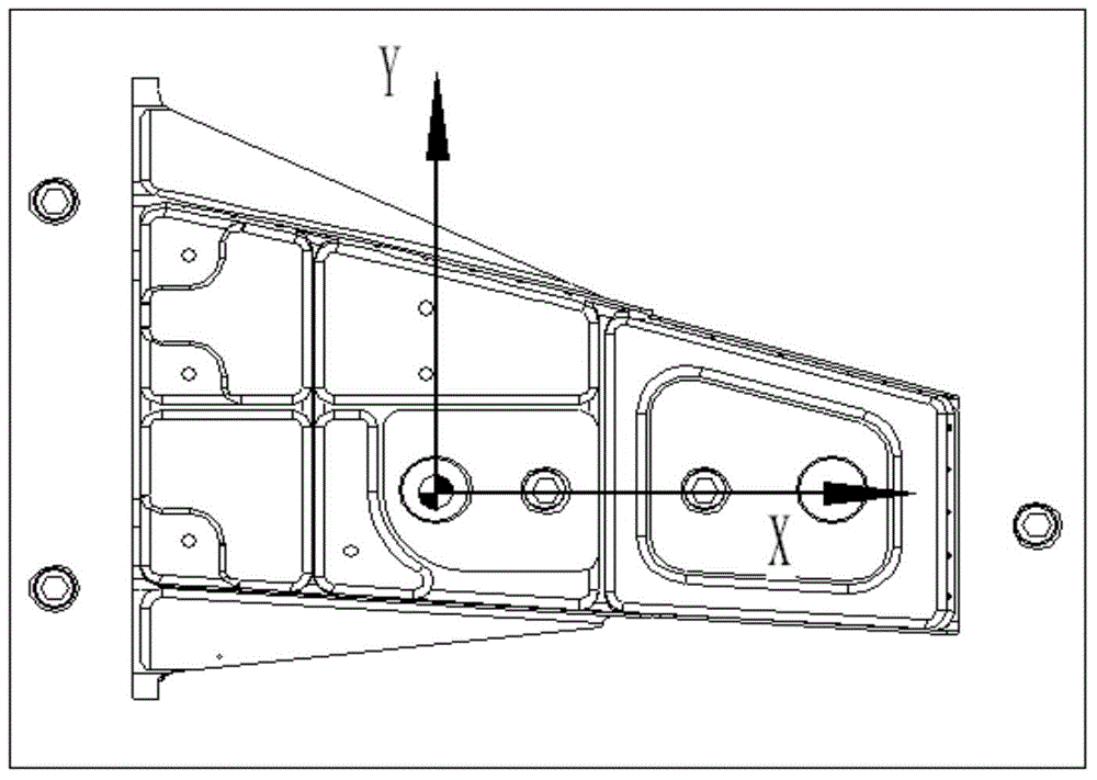
[0033] Select the CNC machining center to process this part. The selected machine tool is the UCP800 five-coordinate CNC machining center. Processing content of the first coordinate system: Z0 value is the bottom surface of the blank. The origin is at the center of the positioning hole, and the X axis is the line connecting the center of the positioning hole with 2-D20H7.

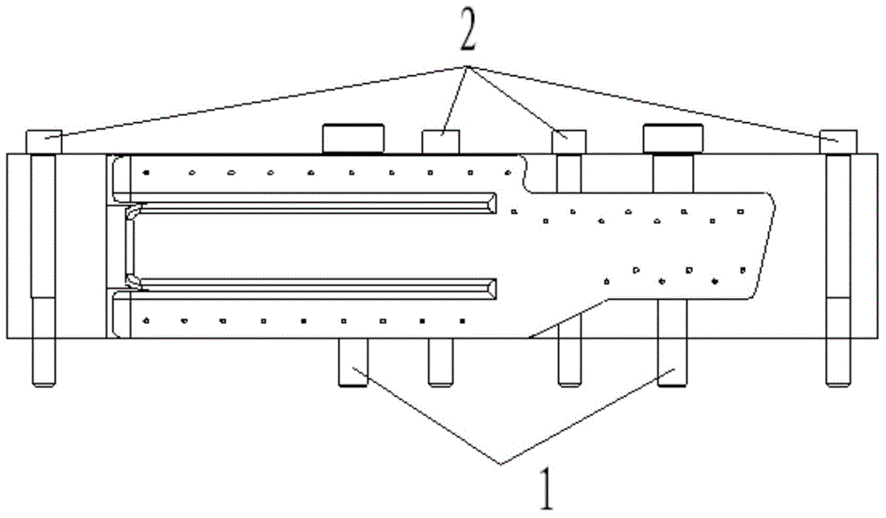
[0034] See the clamping method figure 1 . 1 is two locating pins, 2 is five countersunk bolts, see the figure Image 6 .

[0035] See the first coordinate system figure 2 ...


PUM


Abstract

The invention relates to a machining process method for complex support parts. Two large technical bosses are additionally arranged in two large through cavities in the middle of a web. Two technical holes are additionally formed and used for clamping countersunk bolts. Meanwhile, two positioning holes are additionally formed in the web for positioning parts. Outline cut-off in a pressure plate clamping manner is omitted, and only three technical holes are additionally formed in the outer portion and used for clamping countersunk bolts. The function of rough machining of two surfaces is added. By means of the machining method, dimensional tolerances of the machined parts are within the required dimensional tolerance of a drawing, first pass yield of the parts is effectively ensured, and the part scrap rate is zero. Meanwhile, the machining efficiency of the parts is remarkably improved.

Description

technical field [0001] The invention belongs to the precision mechanical processing technology, and relates to a mechanical processing method for complex support parts. Background technique [0002] Among the machined parts of the helicopter, the support parts are mainly used to connect various machined parts on the aircraft. If the machined parts are the skeleton of the aircraft, then the support parts are the connection points and hubs in the skeleton, so The structure of the support parts is very complex, which also brings considerable difficulties to machining. This support part is a double-sided deep cavity part. The two side walls of the shape of the part are the theoretical shape and the curvature is relatively large, and a semi-closed cavity is added to the side walls of the two shapes, and the other two shape side walls are formed with the bottom web. closed angle. The thickness of the vertical rib and web of the part is basically 1.5mm, and the thinnest wall thic...

Claims


Application Information

Patent Timeline
IPC IPC(8): B23P15/00
CPCB23P15/00B23P2700/01B64C1/00
Inventor 李超路彬耿连昌于银河张凌峰
Owner HARBIN
Why Eureka
Try Eureka