Humanoid lower limbs driven by pneumatic artificial muscles

A pneumatic artificial muscle and human-like technology, applied in the field of humanoid robots and robots, can solve problems such as poor compliance, low energy efficiency of robots, complex system structure, etc., achieve a large power/mass ratio, improve energy efficiency, and simple system structure Effect

Active Publication Date: 2015-11-25
HARBIN INST OF TECH
View PDF6 Cites 19 Cited by
  • Summary
  • Abstract
  • Description
  • Claims
  • Application Information

AI Technical Summary

Problems solved by technology

[0003] The present invention aims to solve the problems that existing active robots are driven by a rigid structure, the system structure is complex,

Method used


Image

  • Humanoid lower limbs driven by pneumatic artificial muscles
  • Humanoid lower limbs driven by pneumatic artificial muscles
  • Humanoid lower limbs driven by pneumatic artificial muscles

Examples


specific Embodiment approach 1

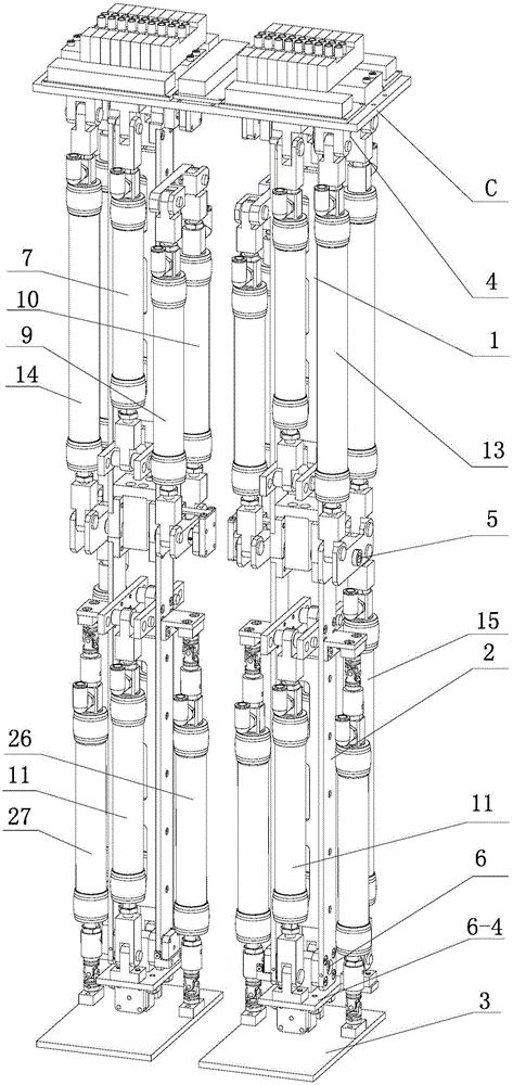
[0011] Specific implementation mode one: combine Figure 1-Figure 8 Explain that a humanoid lower limb driven by pneumatic artificial muscles in this embodiment includes left leg A, right leg B and pelvis C; left leg A and right leg B include thigh 1, calf 2, foot 3, hip Joint 4, knee joint 5, upper ankle joint 61 and lower ankle joint 62;

[0012] The left leg A and the right leg B are connected through the pelvis C, the pelvis 3 is connected with the thigh 1 through the hip joint 4, the thigh 1 is connected with the lower leg 2 through the knee joint 5, and the lower leg 2 is connected with the ankle joint plate 6-4 through the upper ankle joint 61 Rotational connection; the ankle joint plate 6-4 is rotationally connected with the foot 3 through the lower ankle joint 62, the axes of the hip joint axis 4-1, the knee joint axis 5-1 and the upper ankle joint axis 6-1 are parallel, and the upper ankle joint The axial direction of the axis 6-1 is perpendicular to the axial direc...

specific Embodiment approach 2

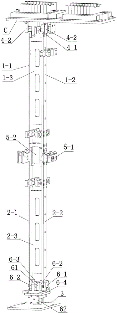
[0017] Specific implementation mode two: combination figure 2 and image 3 Illustrate, each thigh 1 of present embodiment comprises outer thigh board 1-1, inner thigh board 1-2 and thigh support board 1-3; The thigh support plate 1-3 connected by the two, the hip joint 4 includes two first bearing assemblies 4-2, the two first bearing assemblies 4-2 are installed on the pelvis C respectively, and the hip joint shaft 4-1 is rotated and installed on the On the two first bearing assemblies 4-2, the inner leg plate 1-2 and the outer thigh plate 1-1 are respectively connected with the hip joint shaft 4-1. In this implementation, the outer thigh plate 1-1 and the inner thigh plate 1-2 are connected to the hip joint shaft 4-1 through a flat key, so that when the hip joint shaft rotates, the thigh is driven to rotate. Others are the same as in the first embodiment.

specific Embodiment approach 3

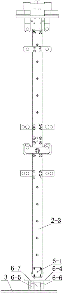
[0018] Specific implementation mode three: combination figure 2 and image 3 Illustrate, each calf 2 of present embodiment comprises calf outer plate 2-1, calf inner plate 2-2 and thigh supporting plate 2-3; The calf support plate 2-3 connected by the two, the knee joint 5 includes the second bearing assembly 5-2, the upper ankle joint 61 includes two third bearing assemblies 6-2, and the lower ankle joint 62 includes two fourth bearing assemblies 6 -5;

[0019] The second bearing assembly 5-2 is fixed on the outer thigh plate 1-1 and the inner thigh plate 1-2, the knee joint shaft 5-1 is installed on the second bearing assembly 5-2, and the upper part of the outer leg plate 2-1 and the top of the calf inner plate 2-2 are respectively fixed on the knee joint shaft 5-1, and the lower parts of the calf outer plate 2-1 and the calf inner plate 2-2 are respectively equipped with a third bearing assembly 6-2, and the upper ankle The joint shaft 6-1 is installed on the two third...


PUM


Abstract

The invention discloses humanoid lower limbs driven by pneumatic artificial muscles and relates to a robot. By the adoption of the humanoid lower limbs driven by the pneumatic artificial muscles, the problems that due to the fact that an existing active robot is driven through a rigid structure, system structure is complicated, flexibility is poor, and the energy efficiency of the robot is low are solved. The humanoid lower limbs comprise a left leg, a right leg and a pelvis, wherein the left leg and the right leg are both provided with a thigh, a shank, a foot, a hip joint, a keen joint, an upper ankle joint and a lower ankle joint, the left leg and the right leg are connected through the pelvis, and the pelvis is connected with the thighs in a rotary mode through the hip joints; each thigh is connected with the corresponding shank in a rotary mode through the corresponding knee joint, each shank is connected with an ankle joint disc in a rotary mode through the corresponding upper ankle joint, and each ankle joint disc is connected with the corresponding foot in a rotary mode through the corresponding lower ankle joint; each thigh is provided with iliacus, gluteus maximus, vastus lateralis muscles, biceps femoris muscles, semitendinosus and rectus femoris, each shank is provided with tibialis anterior muscles, musculi soleus, musculus gastrocnemius, adductor and peroneus, and the upper end of the iliacus and the upper end of the gluteus maximus are both hinged to the pelvis. The humanoid lower limbs belong to the field of humanoid robots.

Description

technical field [0001] The invention relates to a robot and belongs to the field of humanoid robots. Background technique [0002] Humanoid biped robot is a research hotspot in the field of robotics. Biped robot can realize stable walking, running, up and down stairs and other actions. Traditional biped robots, ie active robots, usually use rigid motors and reducers as drive elements, and the control and drive systems are very complex, making the energy efficiency of the robot very low. Contents of the invention [0003] The invention aims to solve the problems that the existing active robot is driven by a rigid structure, the system structure is complicated, the flexibility is poor, and the energy efficiency of the robot is low, and a humanoid lower limb driven by pneumatic artificial muscles is provided. [0004] The technical scheme adopted by the present invention for solving the above problems is: a humanoid lower limb driven by pneumatic artificial muscles, which in...

Claims


Application Information

Patent Timeline
IPC IPC(8): B62D57/032
Inventor 臧希喆刘义祥朱延河刘鑫宇王林
Owner HARBIN INST OF TECH
Why Eureka
Try Eureka