Automatic lifting and transferring machine for painted flat plate jig

An automatic lifting and transfer machine technology, applied in the direction of conveyors, conveyor objects, mechanical conveyors, etc., can solve the problems of material cost waste, increased labor costs, high work intensity, etc., to reduce the risk of fixture damage and improve The effect of improving the level of automation and the flexibility of use

Inactive Publication Date: 2015-11-25
SUZHOU CHUNQIU ELECTRONICS TECH
View PDF11 Cites 2 Cited by
  • Summary
  • Abstract
  • Description
  • Claims
  • Application Information

AI Technical Summary

Problems solved by technology

This brings great disadvantages: one is that the work intensity is high, and frequent moving work will consume a lot of physical strength, otherwise it will be difficult to keep up with the rhythm of the production line, and the increase in manpower will increase labor costs; In the process, there will inevitably be collisions, not only the fixture will be damaged, but also the product will be damaged, resulting in a great waste of material costs

Method used


Image

  • Automatic lifting and transferring machine for painted flat plate jig
  • Automatic lifting and transferring machine for painted flat plate jig
  • Automatic lifting and transferring machine for painted flat plate jig

Examples


Embodiment Construction

[0029] The present invention will be described in further detail below in conjunction with specific embodiments.

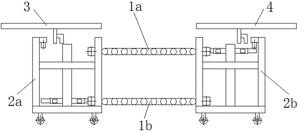
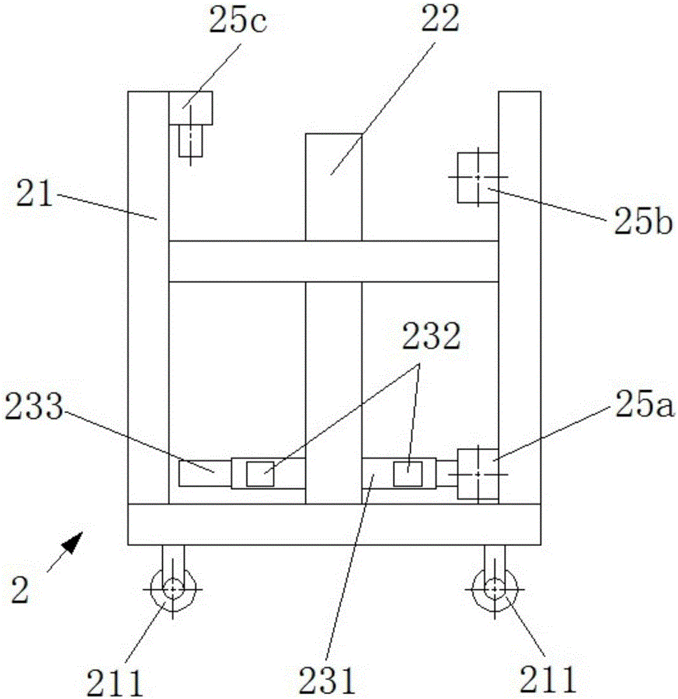
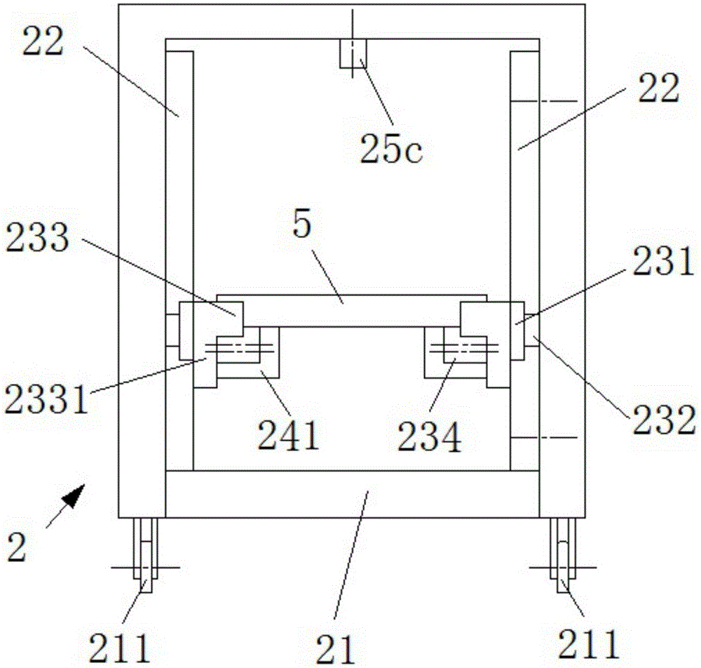
[0030] Such as figure 1 , figure 2 with Figure 5 As shown, an automatic lifting transfer machine for coating flat fixtures of the present invention includes two conveyor belts (first conveyor belt 1a, second conveyor belt 1b) arranged in parallel up and down, two conveyor belts (1a, 1b) A pair of lifting mechanism 2 (the first lifting mechanism 2a, the second lifting mechanism 2b) on the side, the discharging mechanism 3 located at the top of the first lifting mechanism 2a and the reclaiming mechanism 4 located at the top of the second lifting mechanism 2b, lift The mechanism 2 includes a frame 21, a pair of lifting modules 22 vertically arranged on the frame 21, and a material clamping unit 23 controlled by the lifting module 22. The material clamping unit 23 is provided with a material transfer motor 24, and the first conveyor belt 1a and The second conveyo...


PUM


Abstract

The invention provides an automatic lifting and transferring machine for a painted flat plate jig. The machine comprises two conveyor belts which are arranged in parallel at the top and bottom, and a pair of lifting mechanisms arranged at two sides of the conveyor belts, wherein each lifting mechanism comprises a rack, a pair of lifting die sets vertically arranged on the rack, and a clamping unit controlled by the lifting die sets; a material moving motor is arranged on each clamping unit. With the adoption of the machine, the jig can be circularly transferred, thus the degree of automation is improved, the labor cost can be saved, and the risk that the jig is damaged can be reduced.

Description

technical field [0001] The invention relates to the technical field of electronic product manufacturing equipment, in particular to an elevating transfer machine that can automatically complete the cycle of coating flat jigs. Background technique [0002] During the production of the automatic coating line, the jigs supporting the products need to be used in a cycle, and a specific station needs to be set, and the workers will carry the turnover online. This brings great disadvantages: one is that the work intensity is high, and frequent moving work will consume a lot of physical strength, otherwise it will be difficult to keep up with the rhythm of the production line, and the increase in manpower will increase labor costs; In the process, collision will inevitably occur, not only the fixture will be damaged, but also the product will be damaged, resulting in a great waste of material cost. [0003] Therefore, it is necessary to provide a new transfer device to solve the a...

Claims


Application Information

Patent Timeline
IPC IPC(8): B65G37/00B65G47/57
Inventor 胡亚军
Owner SUZHOU CHUNQIU ELECTRONICS TECH
Why Eureka
Try Eureka