Application method of vacuum sputtering coated substrate clamping device

A vacuum sputtering and clamping device technology, which is applied in sputtering coating, vacuum evaporation coating, ion implantation coating, etc., can solve the problems of difficult substrate clamping, complex structure, high efficiency, etc., and achieves easy processing, Strong versatility and the effect of solving diffraction problems

Inactive Publication Date: 2015-11-25
LUOYANG XINZHAO ELECTRON LTD
View PDF3 Cites 3 Cited by
  • Summary
  • Abstract
  • Description
  • Claims
  • Application Information

AI Technical Summary

Problems solved by technology

[0003] The purpose of the present invention is to overcome the mosaic type of the existing ITO vacuum sputtering coating substrate clamping equipment, the structure is complex, and the clamping substrate is slightly difficult. Single-sided and double-sided coating requires two sets of clamping equipment, and it is necessary to improve the mosaic type. The vacuum sputtering coating substrate clamping equipment provides a method of using the vacuum sputtering coating substrate clamping device through reasonable design. The specially designed beam is fixed to the vertical beam through the connecting piece, and the elastic clamp is connected to the beam through screws. On, single-sided products or double-sided products, fixed on the elastic clamp by hand; single-sided and double-sided products, the clamping equipment is compatible, and products of different specifications can be used as long as the beam is moved and re-fixed; the upper and lower stops of the beam Appropriate spacing between the chip and the substrate can prevent diffraction, and the production efficiency is high

Method used


Image

  • Application method of vacuum sputtering coated substrate clamping device
  • Application method of vacuum sputtering coated substrate clamping device
  • Application method of vacuum sputtering coated substrate clamping device

Examples


Embodiment 1

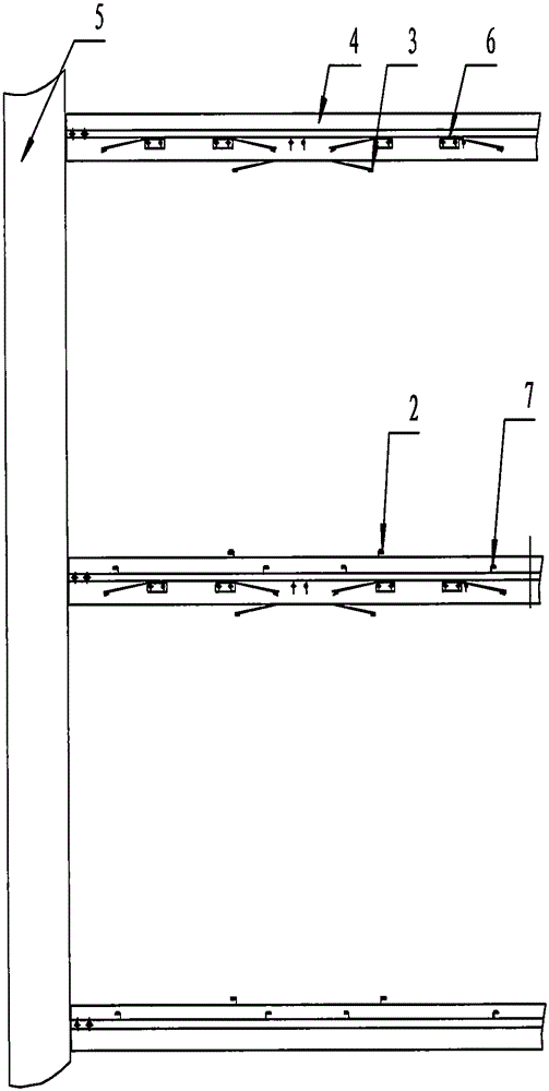
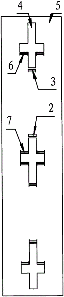
[0018] At least two cross beams 4 are arranged on one side of the vertical beam 5, and the cross beam 4 is set in a cross shape, and side beams are respectively arranged on both sides of the cross beam 4; two double-sided lower elastic cards 2 are arranged symmetrically on the upper side of the middle cross beam 4, and the lower side of the upper cross beam 4 is symmetrical Set two double-sided elastic cards 3, the double-sided elastic card 3 and the double-sided lower elastic card 2 are set correspondingly, and the double-sided substrate 1 is arranged between the double-sided lower elastic card 2 and the double-sided elastic card 3 A group of double-sided elastic cards 3 and double-sided lower elastic cards 2 are arranged under the upper beam 4 and on the middle beam 4; two single-sided elastic cards 6 and the sides of the middle beam 4 are arranged symmetrically under the side beams of the upper beam 4. Two single-sided lower elastic clips 7 are arranged symmetrically on the ...

Embodiment 2

[0021] The single-sided substrate 8 is clamped by the elastic clips 6 on one side and the lower elastic clips 7 on one side, and is fixed between the upper and lower beams 4 on one side of the beam 4; the transport trolley is started, and the transport trolley drives the vertical beam 5 and The beam 4 and the single-sided substrate 8 enter the vacuum sputtering coating box, and the single-sided substrate 8 is sputtered and coated on one side.

Embodiment 3

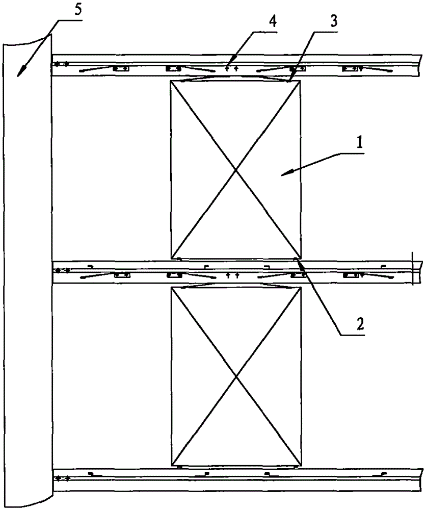
[0023] When processing vacuum sputtering coating on double-sided substrate 1, first put the lower side of double-sided substrate 1 into the slot of double-sided lower elastic card 2 of lower beam 4, and the lower side of double-sided substrate 1 is composed of two double-sided The lower elastic card 2 is symmetrically supported, and then the card slot of the elastic card 3 on both sides of the upper beam 4 is clamped on the upper side of the double-sided substrate 1, and the upper side of the double-sided substrate 1 is supplemented by two symmetrical elastic cards 3 on both sides. tight; the double-sided substrate 1 is clamped by the double-sided elastic clamp 3 and the double-sided lower elastic clamp 2, and is fixed between the upper and lower beams 4 on one side of the beam 4; the conveying trolley is started, and the vertical beam is driven by the conveying trolley 5 and the beam 4 and the double-sided substrate 1 enter the vacuum sputtering coating box, and the double-sid...


PUM


Abstract

The invention provides an application method of a vacuum sputtering coated substrate clamping device. According to the vacuum sputtering coated substrate clamping device, at least two beams are arranged on one side of a vertical beam; each beam is set into a cross shape; side beams are arranged on the two sides of each cross-shaped beam; two double-faced lower elastic clamps are symmetrically arranged on the upper face of the middle beam; the clamping heads of double-faced upper elastic clamps correspond to the clamping heads of the double-faced lower elastic clamps; and a single-faced substrate is arranged between single-sided upper elastic clamps and single-faced lower elastic clamps. When vacuum sputtering coating is conducted, a conveying trolley is started after the upper side of the single-faced substrate is symmetrically clamped by the two single-faced upper elastic clamps in an auxiliary manner, the vertical beam, the beams and a double-faced substrate are driven by the conveying trolley to enter a vacuum sputtering coating box so that spluttering coating can be conducted on the substrates. Single-faced or double-faced coating shares one clamping device, and universality is high; product type replacement is convenient and rapid; the substrates are rapidly assembled and disassembled by hands in a tool-free manner; the diffraction problem is solved, and low-resistance and high-grade products can be produced; and the structure is simple, machining is easy, the manufacturing cost is low, and permanent use is achieved.

Description

technical field [0001] The invention relates to ITO coating processing and production equipment for electronic products, in particular to a method for using a vacuum sputtering coating substrate clamping device. Background technique [0002] The existing ITO vacuum sputtering coating substrate clamping equipment has various forms, including mosaic type and open type. Open type, simple structure, convenient clamping of substrate, strong versatility, and low cost, but the quality of coating products is affected, and high-quality products cannot be produced; mosaic type, complex structure, slightly difficult to clamp substrate, product quality The convenience of clamping the substrate is guaranteed, but the versatility is poor. Each product needs to correspond to a set, which is expensive; no matter whether it is mosaic or open, the versatility of single-sided and double-sided coating is currently not achieved, and two Set clamping equipment; in view of the above reasons, the ...

Claims


Application Information

Patent Timeline
Patent Type & Authority Applications(China)
IPC IPC(8): C23C14/50
Inventor 王新牛建国
Owner LUOYANG XINZHAO ELECTRON LTD
Why Eureka
Try Eureka