Labor-saving linkage positioning and locking structure

A positioning locking and locking mechanism technology, applied in the direction of brake actuators, brake parts, brake types, etc., can solve the problems of small locking stroke, small starting force of roller, large operating torque, etc., to prevent ratchet reverse The effect of small rotation, small driving force and small starting force

Active Publication Date: 2015-11-25
GUIZHOU AEROSPACE TIANMA ELECTRICAL TECH
View PDF5 Cites 8 Cited by
  • Summary
  • Abstract
  • Description
  • Claims
  • Application Information

AI Technical Summary

Problems solved by technology

[0003] However, on the guide rails of vehicles or other motion platforms, due to the small starting force of the rollers, it is easy to move, and it is difficult to perform positioning and locking.
However, the structure using pins for positioning cannot meet the locking transportation requirements, and the fast locking structure cannot provide sufficient locking force. The locking mechanism using camshaft structure needs to provide a large operating torque, and the locking stroke is longer. Small

Method used


Image

  • Labor-saving linkage positioning and locking structure
  • Labor-saving linkage positioning and locking structure
  • Labor-saving linkage positioning and locking structure

Examples


Embodiment Construction

[0020] The technical solution of the present invention is further described below, but the scope of protection is not limited to the description.

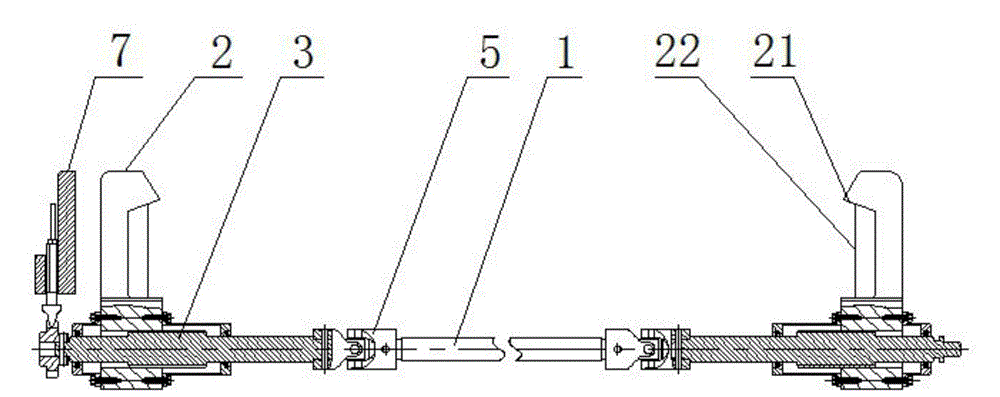
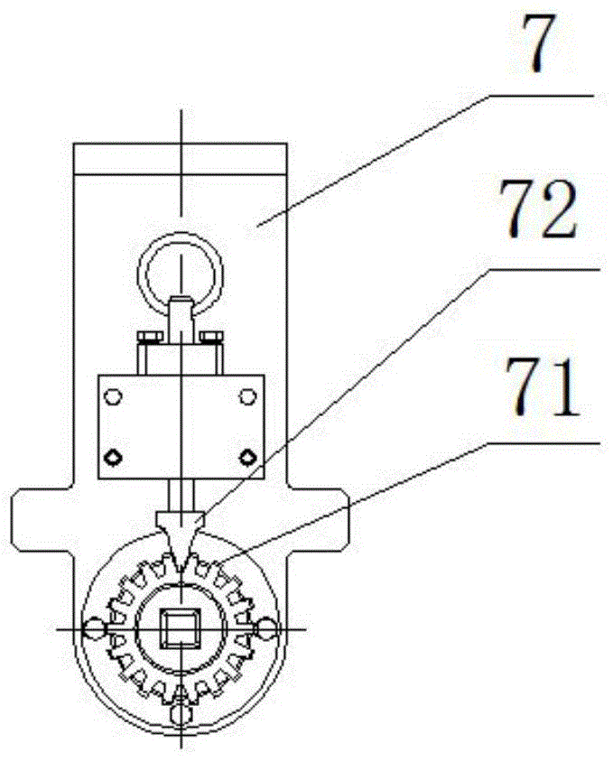
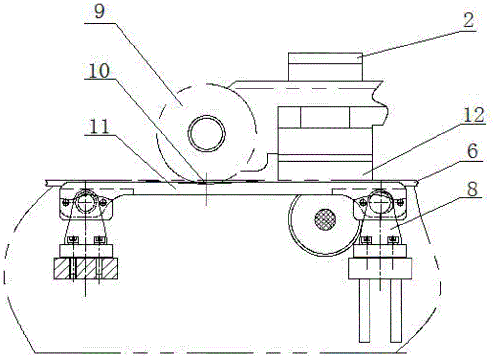
[0021] Such as Figure 1~4 As shown, a labor-saving linkage positioning and locking structure, including connecting rod 1, claw 2, screw rod 3, frame 4, cross universal joint 5, guide rail 6, locking mechanism 7, spring support seat 8, positioning groove 10 and leaf spring 11.

[0022] The guide rail 6 is horizontally installed on the frame 4, and the guide rail 6 is provided with a positioning groove 10, and the positioning groove 10 is a V-shaped groove; the side of the frame is provided with a spring support seat 8, and the spring support seat 8 is provided with a steel plate Spring 11, described leaf spring 11 is juxtaposed parallel with guide rail 6; In order to reduce the horizontal force of leaf spring 11 to spring support seat 8, the connection hole of leaf spring 11 one end is designed as waist-shaped hole.

[0023] The ...


PUM


Abstract

The invention discloses a labor-saving linkage positioning and locking structure, and belongs to the technical field of positioning of machining equipment. The labor-saving linkage positioning and locking structure comprises a connecting rod, clamping jaws, screw rods, a frame, cross universal joints, a guide rail, a locking mechanism, a spring support base, a positioning groove and a steel plate spring, wherein the guide rail is horizontally mounted on the frame; the positioning groove is formed in the guide rail; the spring support base is arranged on the side surface of the frame, and is provided with the steel plate spring; the steel plate spring is parallel to the guide rail; the connecting rod is perpendicular to the guide rail, and is horizontally arranged below the guide rail; the screw rods are respectively connected to the two ends of the connecting rod; the cross universal joints are respectively arranged between the connecting rod and the screw rods; the clamping jaws are respectively matched and mounted on the screw rods at the two ends of the connecting rod; and the tail end of one screw rod is fixedly connected to the locking mechanism. Through the positioning of rollers and the linkage of the clamping jaws, mechanical loads with the rollers achieve a quick, stable and reliable positioning and locking effect on the guide rail for a long time; and the starting force in renewed starting is comparatively low and no scratches of the guide rail may be caused.

Description

technical field [0001] The invention belongs to the technical field of mechanical processing equipment positioning, and relates to a horizontal guide rail roller positioning and locking device used for the limit position of a vehicle-mounted sliding frame, in particular to a labor-saving linkage positioning and locking structure. Background technique [0002] In mechanical equipment with guide rails, in order to reduce the friction between the sliding mechanism and the guide rail, the sliding friction is often replaced by rolling friction by installing rollers, so as to reduce the power requirements of the moving mechanism on the drive system and reduce the movement The mechanism wears on the guide rail. [0003] However, on the guide rails of the vehicle or other motion platforms, because the starting force of the rollers is small, it is easy to move, and it is difficult to perform positioning and locking. However, the structure using the latch for positioning cannot meet ...

Claims


Application Information

Patent Timeline
Patent Type & Authority Applications(China)
IPC IPC(8): F16D71/00F16D65/02F16D65/14F16D121/14F16D125/40
Inventor 梁承锋黄蓉税小龙向振文
Owner GUIZHOU AEROSPACE TIANMA ELECTRICAL TECH
Why Eureka
Try Eureka