Worm and worm gear transmission device

A transmission device, worm gear technology, applied in transmission device parts, transmission box, gear lubrication/cooling, etc., can solve the problem of high work efficiency, achieve high work efficiency, simple structure, and good heat dissipation effect

Inactive Publication Date: 2015-11-25
ECOVACS ROBOTICS (SUZHOU ) CO LTD
View PDF6 Cites 1 Cited by
  • Summary
  • Abstract
  • Description
  • Claims
  • Application Information

AI Technical Summary

Problems solved by technology

[0005] The technical problem to be solved by the present invention is to provide a worm gear transmission for the deficiencies of the prior art. The structure of some components for realizing heat dissipation is very simple. Cooperating with the air inlet and air outlet on the bottom shell, the transmission device An air circulation system is formed inside the bottom shell, which effectively removes the heat generated by the meshing movement of the worm gear and worm, and improves the problem of excessive temperature in the bottom shell of the transmission device at a lower cost. The heat dissipation effect is good and the work efficiency is high.

Method used


Image

  • Worm and worm gear transmission device
  • Worm and worm gear transmission device
  • Worm and worm gear transmission device

Examples


Embodiment Construction

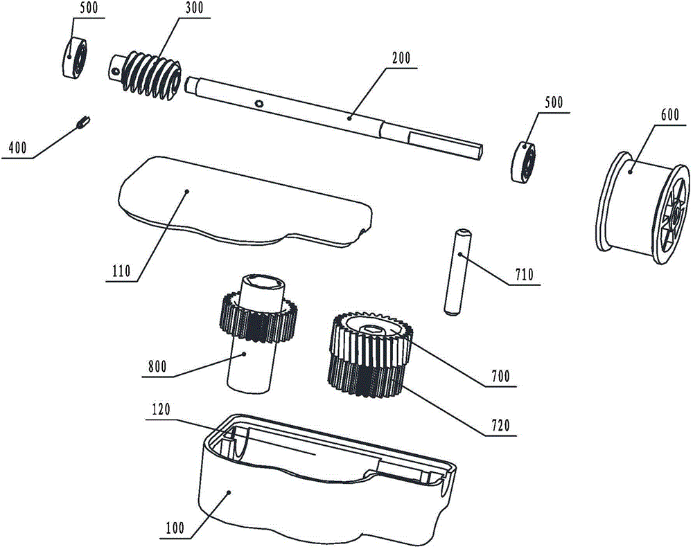
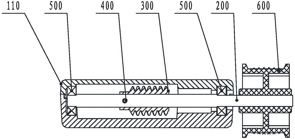
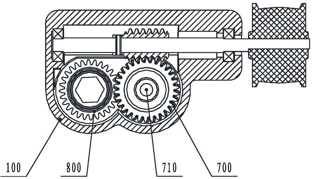
[0028] Figure 4 It is an explosion diagram of the present invention; Figure 5 It is a sectional view of the present invention; Image 6 for Figure 5 top view of Image 6 to omit Figure 4 The output gear 800 in; Figure 7 for Image 6 left view of . combine Figure 4 to Figure 7 As shown, the present invention provides a worm gear transmission with a heat dissipation unit, generally speaking, it includes a casing, and a worm 300 and a worm wheel 700 that are engaged with each other are installed in the housing cavity 120 in the casing. One end of the drive shaft is connected with a first driving device, and the worm gear is connected with the output device. The accommodating cavity 120 is also provided with an impeller 900, the impeller is connected with the second driving device, and rotates under the driving of the second driving device, and the housing is provided with an air inlet 111 and an outlet. Air port 101, under the action of the rotation of the impeller...


PUM


Abstract

Disclosed is a worm-gear transmission device, comprising a housing, and a worm (300) and a worm gear (700) which are engaged with each other and mounted in an accommodating cavity (120) of the housing, wherein one end of a transmission shaft (200) of the worm (300) is connected to a second driving device; the worm gear (700) is connected to an output device; the accommodating cavity (120) is further provided with an impeller (900); the impeller (900) is connected to a second driving device, and can be driven by the second driving device to rotate; and the housing is provided with an air inlet (111) and an air outlet (101), and under rotation of the impeller (900), air flow enters the housing via the air inlet (111), and is discharged from the air outlet (101). The device has a simple structure and low costs. An air circulation system is formed in the interior of a bottom housing (100) of the transmission device, so as to effectively dispel heat generated from the engaging motion of the worm gear (700) and the worm (300), thereby having a good heat dissipation effect and a high operation efficiency.

Description

technical field [0001] The invention relates to a worm gear transmission device, which belongs to the technical field of mechanical manufacturing. Background technique [0002] figure 1 It is an exploded view of the existing worm gear transmission; figure 2 It is a sectional view of an existing worm gear transmission; image 3 for figure 2 top view. Such as Figure 1 to Figure 3 As shown, the existing worm gear transmission device includes a bottom case 100 and an upper cover 110. The transmission shaft 200 is rotatably fixed on the bottom case 100 through ball bearings 500 arranged at both ends, one end is fixed in the bottom case 100, and the other end protrudes It extends out of the bottom case 100 and is fixed with the pulley 600 . The worm 300 is fixed on the transmission shaft 200 through the elastic pin 400 , and the bottom shell 100 is provided with an accommodating cavity 120 , and the worm wheel 700 intermeshing with the worm 300 is fixed in the accommodati...

Claims


Application Information

Patent Timeline
Patent Type & Authority Applications(China)
IPC IPC(8): F16H57/04F16H57/027F16H57/039
CPCF16H57/00F16H57/02F16H57/04F16H57/0416F16H57/027F16H57/039
Inventor 王宣建
Owner ECOVACS ROBOTICS (SUZHOU ) CO LTD
Why Eureka
Try Eureka