Integrally mounted mechanical seal device

A mechanical seal device, cartridge technology, applied in the direction of engine seal, mechanical equipment, engine components, etc., can solve the problems of affecting the service life of the mechanical seal device, large damage to the mechanical seal device, high operator requirements, etc., to achieve savings The effect of shutdown standby time, extended service life and low technical requirements

Inactive Publication Date: 2015-11-25
曹文杰
View PDF9 Cites 5 Cited by
  • Summary
  • Abstract
  • Description
  • Claims
  • Application Information

AI Technical Summary

Problems solved by technology

The mechanical seal device is mainly used for shaft seals. In actual operation, the installation of the mechanical seal device has high requirements for the operator. In addition, the mechanical seal device will generate frictional heat when it rotates with the shaft, and the frictional heat has a great impact on the mechanical seal device. Large damage will affect the service life of the mechanical seal device

Method used


Image

  • Integrally mounted mechanical seal device
  • Integrally mounted mechanical seal device
  • Integrally mounted mechanical seal device

Examples


Embodiment Construction

[0028] The present invention will be further described below in conjunction with the accompanying drawings.

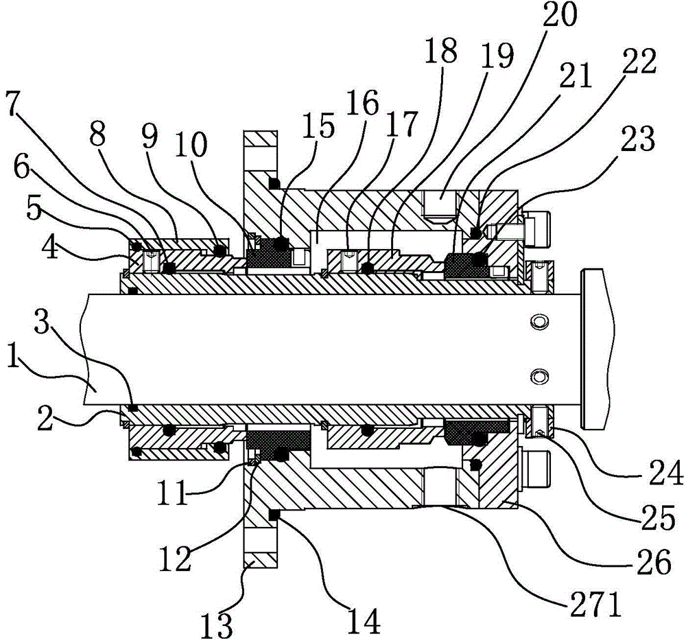
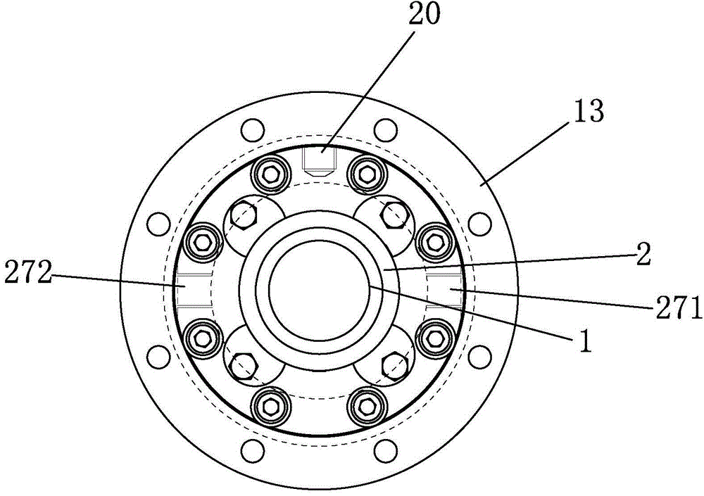
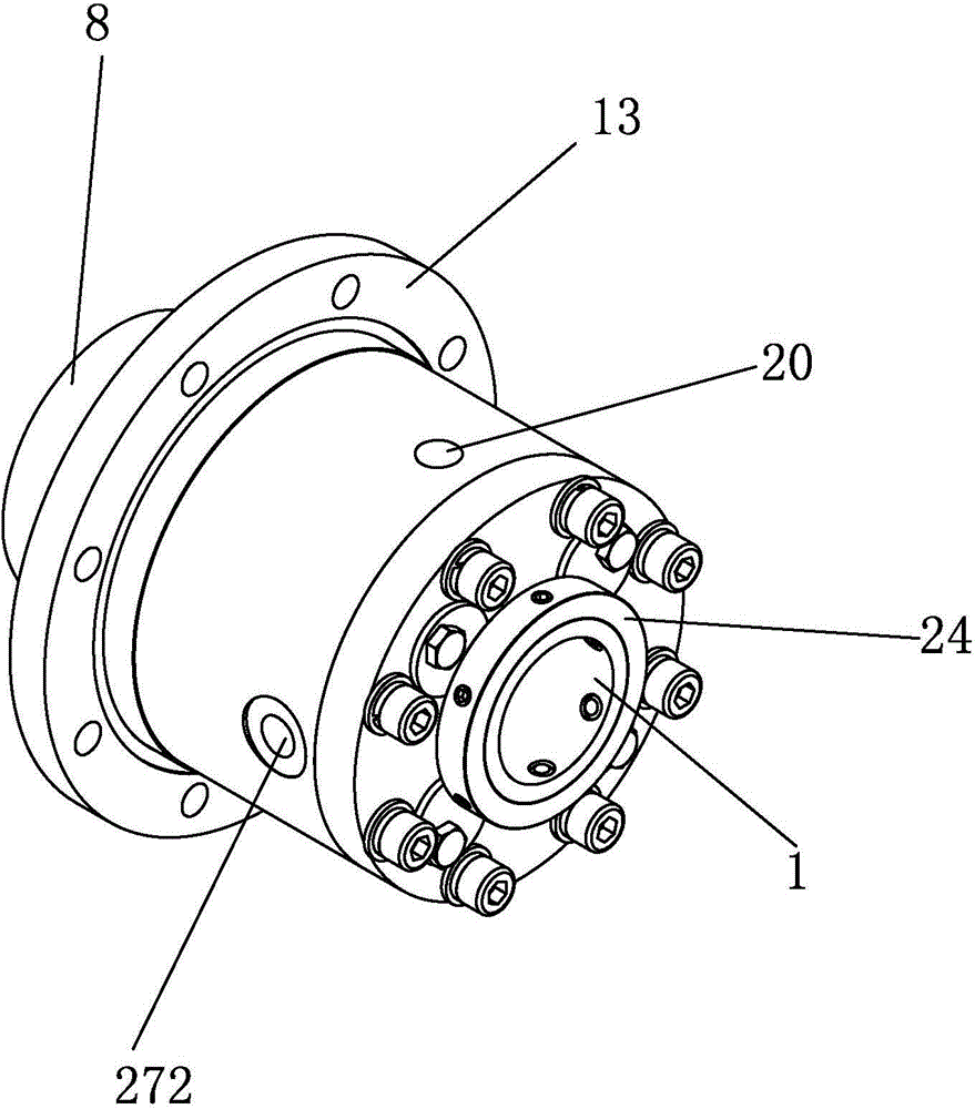
[0029] Such as Figure 1~3 As shown, the present invention discloses a cartridge mechanical seal device including a shaft sleeve 2 sleeved on a main shaft 1 of the equipment. A first sealing assembly and a second sealing assembly are sheathed on the outside of the shaft sleeve 2 in turn. The first sealing assembly includes a first moving ring 4 , and a sleeve 8 is placed around the first moving ring 4 . The second sealing assembly includes a second moving ring 19 , and the second moving ring 19 is provided with a mechanical envelope 13 . A first static ring 10 and a second static ring 21 are respectively provided at both ends of the machine envelope 13 . The end of the first moving ring 4 is attached to the end of the first stationary ring 10, the end of the second moving ring 19 is attached to the end of the second stationary ring 21, and the first stationary ring ...


PUM


Abstract

The invention discloses an integrally mounted mechanical seal device. The integrally mounted mechanical seal device comprises a shaft sleeve, wherein a first seal component and a second seal component sleeve the shaft sleeve, the first seal component comprises a first moving ring and a seal sleeve, the seal sleeve sleeves the first moving ring, the second seal component comprises a second moving ring and a mechanical seal sleeve, the mechanical seal sleeve is arranged outside the second moving ring, a first fixed ring and a second fixed ring are respectively arranged at the two ends of the mechanical seal sleeve, the end portion of the first moving ring is fit with the end portion of the first fixed ring, the end portion of the second moving ring is fit with the end portion of the second fixed ring, and a cooling chamber is arranged in the second seal component. During use, an operator only needs to tightly screw screws into the mechanical seal sleeve and equipment and the installation is facilitated; the first seal component is located inside the equipment, the second seal component is located outside the equipment, friction heat in the first seal component is dissipated through materials, friction heat in the second seal component is dissipated through cooling liquid, the heat dissipating effect is better and the service life of the mechanical seal device is prolonged.

Description

technical field [0001] The invention belongs to a sealing device of a machine conveying fluid medium, and more specifically relates to a cartridge type mechanical sealing device. Background technique [0002] In the dispersing equipment of the electronics and chemical industries that require explosion-proof and harmful gas leakage prevention, it is often necessary to disperse corrosive working media such as high hardness such as silicon dioxide, high viscosity such as epoxy resin, and volatile such as methyl ethyl ketone and acetone. At this time, the sealing performance of the equipment is required to be higher. The mechanical seal device is mainly used for shaft seals. In actual operation, the installation of the mechanical seal device has high requirements for the operator. In addition, the mechanical seal device will generate frictional heat when it rotates with the shaft, and the frictional heat has a great impact on the mechanical seal device. Large damage will affect...

Claims


Application Information

Patent Timeline
Patent Type & Authority Applications(China)
IPC IPC(8): F16J15/34
CPCF16J15/34
Inventor 曹文杰
Owner 曹文杰
Why Eureka
Try Eureka