Valve hydraulic hand wheel

A hydraulic and valve technology, which is applied in the field of valve opening devices, can solve the problems of cumbersome, poor stress, and small installation space, and achieve the effects of broad market prospects, convenient operation, and simple structure

Inactive Publication Date: 2015-11-25
BEIJING AEROSPACE RATE MECHANICAL & ELECTRICAL ENG CO LTD +1
View PDF4 Cites 4 Cited by
  • Summary
  • Abstract
  • Description
  • Claims
  • Application Information

AI Technical Summary

Problems solved by technology

[0004] 1. When a large handwheel is used, first of all, it is inconvenient for one person to operate. According to the relevant calculation of the valve, when the diameter of the handwheel reaches a certain level, the torque generated by one person will not increase, and two or more people may be needed. In addition, the installation space of high-pressure valves in some places is small, but the diameter of the required handwheel is large, resulting in problems that cannot be installed or the manual operation is cumbersome; finally, the valve head of the large-diameter handwheel is large, and the appearance is not beautiful.
[0005] When using a small pitch thread, the stress situation is not good, it is necessary to use a thicker screw, and the number of turns of the hand wheel is large, which is inconvenient to design and use.
[0006] 2. The turbine and worm mechanism is adopted. This mechanism adopts a relatively large worm gear and worm transmission, and drives the turbine mechanism with a small force to generate a large force. The cost of this mechanism is relatively high, and half of it is now a casting product, which is heavy and not only increases the number of valves. The weight of the valve increases the overall cost of the valve, making it difficult to install and maintain the valve, and the maintenance cost is relatively high
[0007] 3. The use of electric, pneumatic and other automation systems requires a certain amount of basic investment, such as electricity and gas, etc., the cost is high, especially in remote areas, it is particularly difficult, and there are certain risks in use
[0008] 4. Some valves need to be closed manually and quickly

Method used


Image

  • Valve hydraulic hand wheel

Examples


Embodiment approach

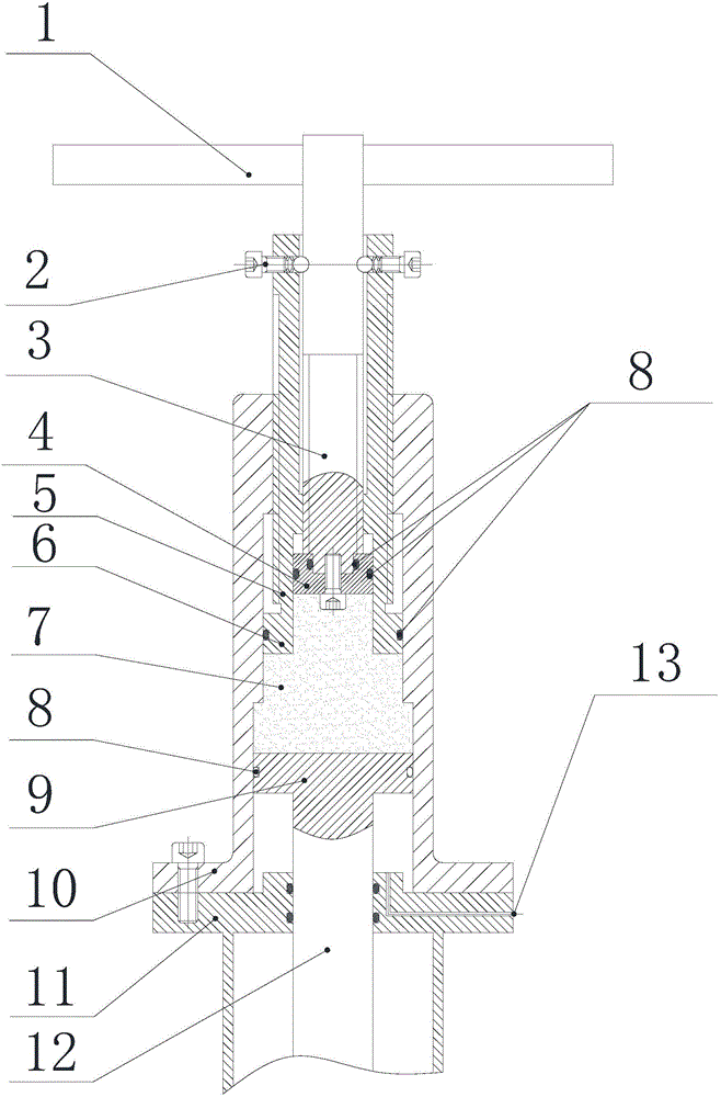
[0054] As a preferred embodiment of the present invention, the valve body 11 is provided with a vent hole 13, and the vent hole 13 is arranged at the joint between the valve body 11 and the housing 10; the vent hole 13 communicates with the driven valve stem piston 9 The area between the valve body 11 and the external environment. The main function of the vent hole 13 of the present invention is to prevent the lower end of the driven valve rod piston 9 from holding pressure, causing difficulty in closing. At the same time, when the valve is opened, the atmospheric pressure can be used to lift the valve rod. It is not very sealed to be connected with the valve body, and the same effect can also be achieved.

[0055] It should be understood by those skilled in the art that the present invention has the following three usage states:

[0056] 1. When the valve needs to be closed quickly at the initial stage of closing, A>A2;

[0057] 2. When the valve needs to be closed synchron...


PUM


Abstract

The invention provides a valve hydraulic hand wheel. The valve hydraulic hand wheel comprises a driving valve rod, a driven valve rod and a shell. One end of the driving valve rod is arranged in the shell, and the other end of the driving valve rod extends out of the shell. A driving valve rod piston is arranged at the end, arranged in the shell, of the driving valve rod. One end of the driven valve rod is arranged in the shell, and the other end of the driven valve rod extends out of the shell and is connected with a valve element of a valve. A driven valve rod piston is arranged at the end, arranged in the shell, of the driven valve rod. A liquid medium is sealed between the driving valve rod piston and the driven valve rod piston. The driving valve rod drives the driven valve rod to move through the hydraulic action of the liquid medium. The driven valve rod drives the valve element to move so that the valve can be opened or closed. The hydraulic mode is adopted in the valve hydraulic hand wheel, on the basis of the pascal law, the driving valve rod is driven to move, the liquid medium is pushed by the driving valve rod piston so that the pressure intensity can be generated in the liquid medium and the driven piston rod piston can be pushed, the driven valve rod drives the valve element to move, and the valve is opened or closed.

Description

technical field [0001] The invention relates to the field of valve opening devices, in particular to a valve hydraulic handwheel. Background technique [0002] During the use of manual valves, due to the large sealing and opening torque required for large-diameter valves and high-pressure valves, the current solutions are: 1. Use larger handwheels (or use small pitch thread transmission); 2. Use worm gear mechanism; 3. Adopt automation systems such as motors and pneumatics. [0003] The disadvantages of the above methods are: [0004] 1. When a large handwheel is used, first of all, it is inconvenient for one person to operate. According to the relevant calculation of the valve, when the diameter of the handwheel reaches a certain level, the torque generated by one person will not increase, and two or more people may be needed. In addition, the installation space of high-pressure valves in some places is small, but the diameter of the required handwheel is large, resulting...

Claims


Application Information

Patent Timeline
Patent Type & Authority Applications(China)
IPC IPC(8): F16K31/60
CPCF16K31/60
Inventor 滕磊军任宏杰申靖李亚鹏
Owner BEIJING AEROSPACE RATE MECHANICAL & ELECTRICAL ENG CO LTD
Why Eureka
Try Eureka