
LED mining lamp

A technology of LED industrial and mining lamps and LED light sources, applied in lighting devices, cooling/heating devices of lighting devices, electric light sources, etc., can solve problems that do not conform to the concept of green recycling and environmental protection, small parts and whole lamps are scrapped, and packaging materials are expensive. , to achieve unique and novel structural design, facilitate later maintenance and save packaging materials

Inactive Publication Date: 2015-11-25
中山市古镇鸿锋彩印厂
View PDF0 Cites 1 Cited by
  • Summary
  • Abstract
  • Description
  • Claims
  • Application Information

AI Technical Summary

Problems solved by technology

[0003] Existing LED industrial and mining lamps generally include a lamp body structure, a reflector, a light source structure and a light-transmitting cover. When the whole lamp is assembled, the height is high and the volume is large. The production cost of LED industrial and mining lights, and the transportation is inconvenient, and even the parts are broken, it is troublesome to repair and replace, or the small parts are broken and difficult to disassemble and replace, resulting in the whole lamp being scrapped, which does not conform to the green cycle environmental protection concept advocated by LED, and shortens the life of the lamp. Service life of LED industrial and mining lights
[0004] At the same time, the LED light source emits light as a point light source, which is a direct-to-outward light emitting method. This design leads to uneven distribution of illumination light intensity, and the small light output surface of the LED light source results in a narrow working area for illumination. The light that cannot be irradiated to the work surface becomes light pollution. And the light intensity distribution is excessively concentrated to cause light spots on the ground, which is easy to produce glare and make people feel dizzy, which affects people's normal work and poses a threat to the personal safety of workers working on the site.

Method used


Image

  • LED mining lamp
  • LED mining lamp
  • LED mining lamp

Examples


Embodiment Construction

[0022] It should be understood that the specific embodiments described here are only used to explain the present invention, not to limit the present invention.

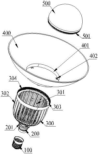
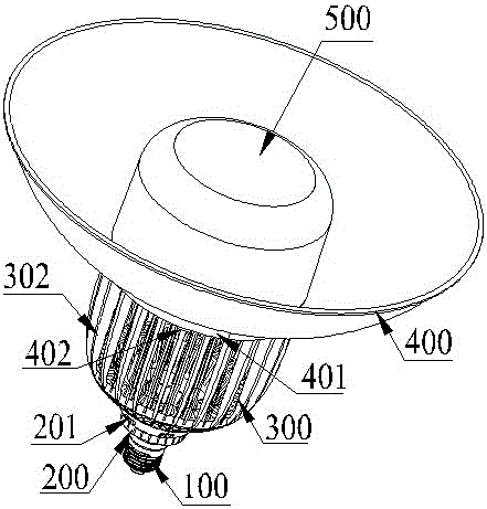
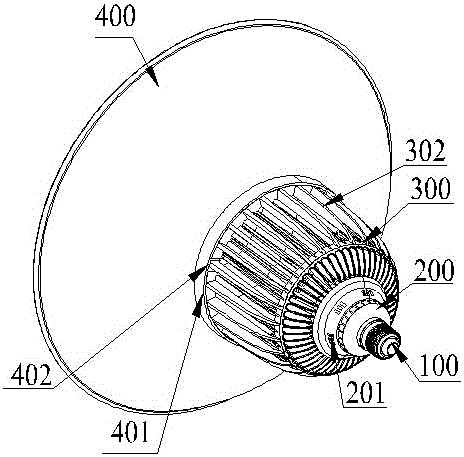
[0023] refer to Figure 1 to Figure 3 , an embodiment of an LED industrial and mining lamp of the present invention is proposed, including a lamp body structure, a reflector 400 that is fixed on the lamp body structure through a snap-fit ​​connection and is in the shape of a trumpet upwards, and is arranged on the lamp body structure The LED light source structure at the end face and irradiating outwards, the light-transmitting cover 500 covering the LED light source structure, the lamp body structure includes a lamp cap 100, and a lamp cap holder 200 connected to the lamp cap 100, and the lamp cap seat 200 extends upwards to a middle setting The lamp body 300 is a hollow cavity 301. The outer wall of the lamp body 300 is composed of several heat dissipation strips 302 arranged in a hollow structure. The upper opening...


PUM


Abstract

The invention discloses an LED mining lamp. The LED mining lamp comprises a lamp structure, a reflector which is upwards in a horn shape, an LED light source structure irradiating outwards, and a light transmitting cover. The lamp structure comprises a lamp holder and a lamp holder base connected with the lamp holder. The lamp holder base extends upwards to form a lamp body. A plurality of cooling strips of a hollow structure are arranged on the outer side wall of the lamp body. A light source groove capable of containing the LED light source structure is formed in an opening in the upper end of the lamp body. An inner thread is arranged on the inner side wall of the light source groove. An outer thread which is matched with the inner thread and can be in threaded connection to enable the LED light source structure to be covered with the light transmitting cover is arranged at an opening in the lower end of the outer side wall of the light transmitting cover. The light transmitting cover is in a half-ball shape or cylinder shape. The bottom in the reflector extends downwards to form an installing ring. The inner side wall of an opening in the lower end of the installing ring extends inwards to form a plurality of U-shaped clamping blocks which are matched with the cooling strips and can be clamped with the cooling strips to clamp and fix the reflector to the lamp body. The LED mining lamp is simple in structure, good in cooling effect, convenient to mount and dismount, small in packaging size, convenient to transport and good in lighting effect.

Description

technical field [0001] The invention relates to the field of LED lighting, in particular to an LED industrial and mining lamp. Background technique [0002] Construction sites, pipelines, mining areas, etc. generally use industrial and mining lamps as lighting tools to illuminate the entire working surface. Traditionally, high-power incandescent lamps, tungsten halogen lamps, high-intensity gas discharge lamps or a large number of fluorescent lamps are used. These lamps consume High energy, short life, in the environment of global resource shortage and green environmental protection, it has been gradually eliminated and replaced by LED high bay lights with low energy consumption, small size, high stability, fast response and long life. LED industrial and mining lamps have high light intensity and concentrated light irradiation can provide construction workers with a good line of sight and good safety. [0003] Existing LED industrial and mining lamps generally include a lam...

Claims


Application Information

Patent Timeline
Patent Type & Authority Applications(China)
IPC IPC(8): F21S2/00F21V7/22F21V17/12F21V17/16F21V29/83F21V29/89
CPCF21S2/00F21V7/22F21V17/12F21V17/164
Inventor 陈德见
Owner 中山市古镇鸿锋彩印厂
Learn More