Comprehensive water-saving and energy-saving system for generator sets

A technology for generator sets and energy-saving systems, which is applied in the direction of machines using waste heat, machine operation methods, and climate change adaptation. It can solve problems such as high load of decompression equipment, large difference in specific gravity, and impact on heat exchange efficiency, and achieve condensation load. Reduce and highlight the effect of energy saving and high heat exchange efficiency

Active Publication Date: 2017-04-05
李永堂 +1
View PDF7 Cites 0 Cited by
  • Summary
  • Abstract
  • Description
  • Claims
  • Application Information

AI Technical Summary

Problems solved by technology

Its main disadvantages are: first, the heat from the discharged exhaust steam from about 40-50 ° C to the liquid phase process, especially the phase change heat, is not used, resulting in energy waste; second, the use of water for exhaust steam containing high heat energy Condensation results in huge water consumption and consumes a lot of water resources
Its main disadvantages are: first, the composition of the non-condensable gas is relatively complex, and the specific gravity varies greatly. Only part of the non-condensable gas can be removed from the condenser space, and the rest is still trapped in the condenser, which affects the heat exchange efficiency; Second, to achieve the set vacuum degree, the load of the decompression equipment is too high, resulting in waste of energy

Method used


Image

  • Comprehensive water-saving and energy-saving system for generator sets
  • Comprehensive water-saving and energy-saving system for generator sets

Examples


Embodiment 1

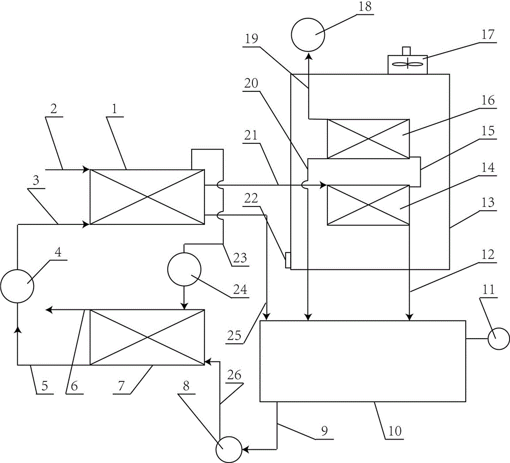
[0024] Such as figure 1 As shown, this embodiment includes a first heat exchanger 1 and a second heat exchanger 7, the intake end of the first heat exchanger 1 is connected with a exhaust steam inlet pipe 2, and the refrigerant outlet of the first heat exchanger 1 A compressor 24 is connected through a refrigerant air pipe 23, the exhaust end of the compressor 24 is connected to the refrigerant inlet of the second heat exchanger 7, and the refrigerant outlet of the second heat exchanger 7 is connected to a joint through the refrigerant A liquid pipe 5. The flow valve 4 and the throttle valve 4 are connected to the refrigerant inlet of the first heat exchanger 1 through the refrigerant B liquid pipe 3 .

[0025] The liquid discharge end of the first heat exchanger 1 is connected with the liquid storage tank 10 through the liquid discharge pipe 25, and also can not set the liquid discharge pipe 25 when the liquid discharge amount of the first heat exchanger 1 is less, the first ...

Embodiment 2

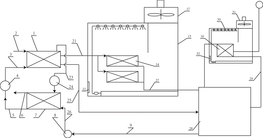
[0035] Such as figure 2 As shown, this embodiment includes a first heat exchanger 1 and a second heat exchanger 7, the intake end of the first heat exchanger 1 is connected with a exhaust steam inlet pipe 2, and the refrigerant outlet of the first heat exchanger 1 A compressor 24 is connected through a refrigerant air pipe 23, the exhaust end of the compressor 24 is connected to the refrigerant inlet of the second heat exchanger 7, and the refrigerant outlet of the second heat exchanger 7 is connected to a joint through the refrigerant A liquid pipe 5. The flow valve 4 and the throttle valve 4 are connected to the refrigerant inlet of the first heat exchanger 1 through the refrigerant B liquid pipe 3 . The liquid discharge end of the first heat exchanger 1 is connected with a liquid reservoir 28 through a liquid discharge pipe 25. When the liquid discharge of the first heat exchanger 1 is less, the liquid discharge pipe 25 may not be set. The first heat exchanger 1 The disch...


PUM


Abstract

The invention discloses a comprehensive water-saving and energy-saving system for a power generation set. A dead stream intake pipe is connected to the air inlet end of a first heat exchanger. A compressor is connected to a refrigerant outlet and connected with a refrigerant inlet of a second heat exchanger. A refrigerant outlet of the second heat exchanger is connected with a refrigerant inlet of the first heat exchanger. The comprehensive water-saving and energy-saving system for the power generation set further comprises a condensation shell and a third heat exchanger mounted in the condensation shell. The tube pass or plate pass of the third heat exchanger is connected with the air outlet end of the first heat exchanger. The comprehensive water-saving and energy-saving system for the power generation set further comprises a fourth heat exchanger, wherein the air outlet end of the fourth heat exchanger is connected with a decompression device. An outlet of the third heat exchanger is connected with a liquid storage tank and the fourth heat exchanger; or the outlet end of the third heat exchanger is connected with a liquid storage device, and a gas-phase outlet of the liquid storage device is connected with the fourth heat exchanger. The liquid storage tank or the liquid storage device is connected with the second heat exchanger, and the water outlet end of the second heat exchanger is connected with a high-temperature water supply pipe. The phase-change heat energy of dead steam exhausted by the power generation set is extracted to be used for heating condensate water of the system, and thus the purpose of comprehensive water saving and energy saving is realized.

Description

technical field [0001] The invention relates to a comprehensive water-saving and energy-saving system for generating sets. [0002] technical background [0003] The temperature of the exhaust steam discharged from the generator set is generally around 40-50°C. This part of the exhaust steam becomes water after being condensed in a vacuum. It is pumped into the boiler by a water pump or heated and pressurized by other heating systems to become high-temperature and high-pressure steam. The generator set does work. Its main disadvantages are: first, the heat from the discharged exhaust steam from about 40-50 ° C to the liquid phase process, especially the phase change heat, is not used, resulting in energy waste; second, the use of water for exhaust steam containing high heat energy Condensation results in huge water consumption and consumes a lot of water resources. [0004] In addition, the exhaust steam discharged from the generator set contains a large amount of non-conde...

Claims


Application Information

Patent Timeline
Patent Type & Authority Patents(China)
IPC IPC(8): F25B27/02
CPCY02A30/274
Inventor 李永堂
Owner 李永堂
Why Eureka
Try Eureka