
Vapor condensing and recovering device

A technology for condensation recovery and water vapor, which is applied in steam/steam condensers, lighting and heating equipment, etc., can solve the problems of inability to guarantee crude oil coils, increase labor intensity of employees, and increase the frequency of water replenishment, and achieve reasonable structure and high recovery rate High, reduce the effect of adding water

Active Publication Date: 2015-11-25
PETROCHINA CO LTD
View PDF5 Cites 2 Cited by
  • Summary
  • Abstract
  • Description
  • Claims
  • Application Information

AI Technical Summary

Problems solved by technology

[0003] The purpose of the present invention is to overcome the problem that the water vapor produced by the existing well group water boiling furnace directly escapes from the water inlet, causing the water level in the furnace to drop, and it is impossible to ensure that the crude oil coil is always in the state of being submerged in water in the furnace, which in turn leads to a decrease in the water level in the furnace , the frequency of water replenishment increases, increases the labor intensity of employees, and also causes the problem of waste of water resources

Method used


Image

  • Vapor condensing and recovering device
  • Vapor condensing and recovering device
  • Vapor condensing and recovering device

Examples


Embodiment 1

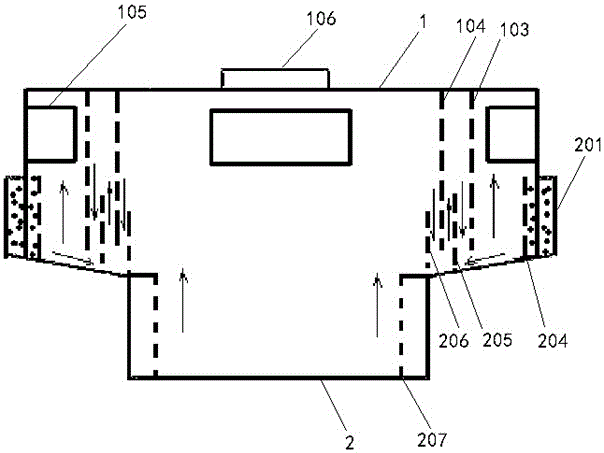
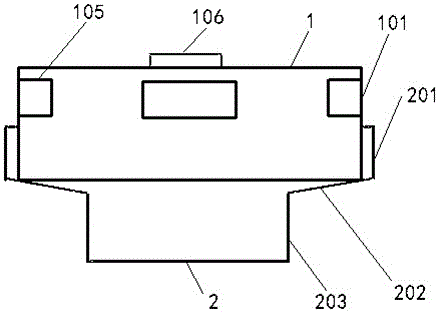
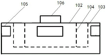
[0025] A water vapor condensation recovery device, comprising an upper cover 1 and a lower cover 2, such as image 3 with Figure 4 As shown, the upper cover 1 includes a cylindrical body 101, one end of the cylindrical body 101 is open, and the other end is sealed by the top plate 102, and the cylindrical body 101 is provided with welding on the top plate 102 and coaxial with the cylindrical body 101. The upper-level annular plate 103 and the upper secondary annular plate 104, the upper secondary annular plate 104 is located in the upper-level annular plate 103; as Figure 5 with Image 6 As shown, the lower cover 2 includes an outer ring annular plate 201, a truncated circular plate 202, and a bottom annular plate 203. One end of the small diameter of 202 is connected with the end of the bottom annular plate 203, and the lower cover 2 is provided with a lower secondary annular plate 204, a lower third-level annular plate 205 and a lower fourth-level annular plate 206 in se...

Embodiment 2

[0030] On the basis of Example 1, such as figure 1 As shown, the space between the outer annular plate 201 and the lower secondary annular plate 204 is filled with water. The water vapor turns back multiple times in the water vapor condensation recovery device, and the water vapor in the device is condensed into water droplets under the cooling effect of the water between the outer annular plate 201 and the next secondary annular plate 204 and the external flowing air, And recycling, at the same time, the water between the outer annular plate 201 and the lower secondary annular plate 204 can ensure a good seal when the upper cover 1 and the lower cover 2 are embedded.

Embodiment 3

[0032] On the basis of Embodiment 1, in order to facilitate the flow of water droplets into the water inlet, the bottom ends of the lower secondary annular plate 204, the lower third-stage annular plate 205 and the lower fourth-stage annular plate 206 are in contact with the inner surface of the cone-shaped annular plate 202 There are multiple holes everywhere. Specifically, the water vapor turns back multiple times in the water vapor condensation recovery device, and under the cooling effect of the external flowing air, the water vapor in the device is condensed into water droplets, and flows into the water inlet from the hole for recycling and saving water resources, and reduce the number of staff replenishing water.


PUM


Abstract

The invention provides a vapor condensing and recovering device which can cover a water filling opening of a well group water boiling furnace directly, collect vapor and condense the vapor into water. The device is like multiple concentric shielding rings in shape, and vapor is made to turn back in the device multiple times and is condensed into water drops under the cooling effect of mobile air outside the outermost ring. The water drops flow into a furnace body from holes of the device, and accordingly, it is guaranteed that water in the furnace is sufficient; the device has the advantages of being capable of saving water, reasonable in structure, convenient to use, high in recovery rate and capable of reducing water adding frequency for workers at the station and reducing the labor intensity.

Description

technical field [0001] The invention belongs to the technical field of crude oil heating equipment in the petroleum industry, and in particular relates to a water vapor condensation recovery device installed at a water inlet of a water boiling furnace in a well group. Background technique [0002] The crude oil heating equipment commonly used in oil production sites is the well group water boiling furnace. As the water temperature in the furnace rises, a large amount of water vapor is generated and escapes from the water inlet, causing the water level in the furnace to drop. In the state of water submerged in the furnace. Crude oil coils exposed in humid environments are prone to rust. The water level in the furnace decreases, the frequency of water replenishment increases, the labor intensity of employees is increased, and water resources are wasted. Contents of the invention [0003] The purpose of the present invention is to overcome the problem that the water vapor p...

Claims


Application Information

Patent Timeline
Patent Type & Authority Applications(China)
IPC IPC(8): F28B1/06F28B1/02
Inventor 闫民力李学琴杨君闫民亮周维琴张小梅陈凤莲
Owner PETROCHINA CO LTD
Learn More