
Automatic calibration circuit and calibration method for fiber grating demodulator F-P filter

A technology of fiber grating demodulation and automatic calibration, which is applied in the direction of instruments, can solve the problems of F-P filter temperature influence, manpower consumption, and resolution reduction, so as to ensure normal operation, eliminate creep, and high resolution Effect

Active Publication Date: 2015-11-25
NANJING NARI GROUP CORP +1
View PDF5 Cites 1 Cited by
  • Summary
  • Abstract
  • Description
  • Claims
  • Application Information

AI Technical Summary

Problems solved by technology

[0006] (1) The scanning voltage needs to be adjusted manually
[0007] Since the scanning voltage range of each F-P filter corresponding to the wavelength between 1525 and 1565nm is not fixed, the driving voltage range of the F-P filter is currently adjusted manually, which is extremely time-consuming and laborious.
[0008] (2) F-P filter is greatly affected by temperature
[0009] At different temperatures, the scanning voltage range of each F-P filter corresponding to the wavelength between 1525 and 1565nm is not fixed. It is necessary to determine the scanning voltage range of the F-P filter at high and low temperature respectively, and take the scanning voltage at high and low temperature The union of the range, so as to meet the normal measurement at high temperature, which will greatly reduce the resolution of the measurement, and the whole calibration process consumes a lot of manpower

Method used


Image

  • Automatic calibration circuit and calibration method for fiber grating demodulator F-P filter
  • Automatic calibration circuit and calibration method for fiber grating demodulator F-P filter

Examples


Embodiment Construction

[0028] The present invention will be further described below in conjunction with the accompanying drawings. The following examples are only used to illustrate the technical solution of the present invention more clearly, but not to limit the protection scope of the present invention.

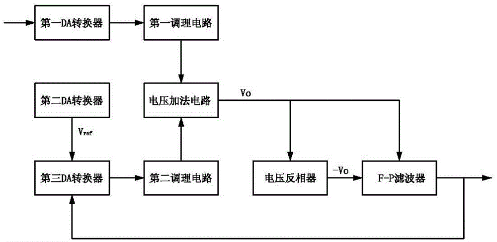
[0029] Such as figure 1 As shown, the automatic calibration circuit of the F-P filter of the fiber grating demodulator includes a starting voltage circuit, a scanning voltage circuit, a voltage adding circuit and a voltage inverter.

[0030] The starting point voltage circuit includes: a first DA converter connected to the CPU and a first conditioning circuit connected to the output end of the first DA converter.

[0031] The scanning voltage circuit includes: a third DA converter for controlling the scanning voltage range of the F-P filter, a second DA converter for providing a reference voltage for the third DA converter, and a second DA converter connected to the output terminal of the third...


PUM


Abstract

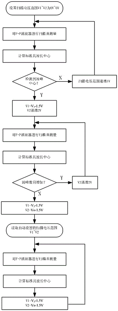
The invention discloses an automatic calibration circuit for a fiber grating demodulator F-P filter. A CPU controls the output voltage of a first DA converter to reach a starting voltage; the output voltage of a second DA converter serves as a reference voltage of a third DA converter; adjustable range of the output voltage of the third DA converter is realized by adjusting the output voltage of the second DA converter; and a voltage adder enables the starting voltage and a scanning voltage to be superposed, and then, through phase inversion of a voltage phase inverter, the voltage drives the F-P filter. The invention further discloses an automatic calibration method for the fiber grating demodulator F-P filter. The method is characterized by, in the operation process, calculating a center voltage V3 of the first peak and a center voltage V4 of the last peak of an etalon after each scanning measurement; and controlling the range V1-V2 of the output voltage Vo of the voltage adder to be from V3-1.5 V to V4+1.5 V. The method can determine the voltage scanning range of the F-P filter automatically, thereby saving time and labor.

Description

technical field [0001] The invention relates to an automatic calibration circuit for an F-P filter of an optical fiber grating demodulator, and also relates to an automatic calibration method for an F-P filter of an optical fiber grating demodulator, belonging to the technical field. Background technique [0002] As a new generation of sensors, fiber optic sensors can measure many physical quantities, chemical quantities and biomass with high resolution, and can realize the measurement of on-site non-electrical measurements, which essentially solves the problem of flammability and flammability that traditional electrical sensors are difficult to get involved in. It can detect the safety measurement of explosive and strong electromagnetic field places; it can conveniently, accurately and effectively detect the relevant physical quantities, chemical quantities and biomass in various environments, especially in various harsh environments. In addition, the optical fiber has a la...

Claims


Application Information

Patent Timeline
Patent Type & Authority Applications(China)
IPC IPC(8): G01D18/00
Inventor 李桂平安保庆景波云熊光亚华涛罗孝兵郑水华
Owner NANJING NARI GROUP CORP
Learn More