
Shielded wire, harness, electrical circuit, fabric, garment and sheet

A wire and cloth technology, applied in the fields of cloth, clothes and sheets, shielded wires, circuits, and wire harnesses, can solve problems such as central conductor disconnection

Inactive Publication Date: 2015-11-25
HITACHI METALS LTD
View PDF1 Cites 0 Cited by
  • Summary
  • Abstract
  • Description
  • Claims
  • Application Information

AI Technical Summary

Problems solved by technology

[0008] However, in conventional shielded electric wires, there is a problem that the central conductor tends to be broken when it is sewn into the cloth-like material with a sewing machine.

Method used


Image

  • Shielded wire, harness, electrical circuit, fabric, garment and sheet
  • Shielded wire, harness, electrical circuit, fabric, garment and sheet

Examples


Embodiment Construction

[0025] Embodiments of the present invention will be described below with reference to the drawings.

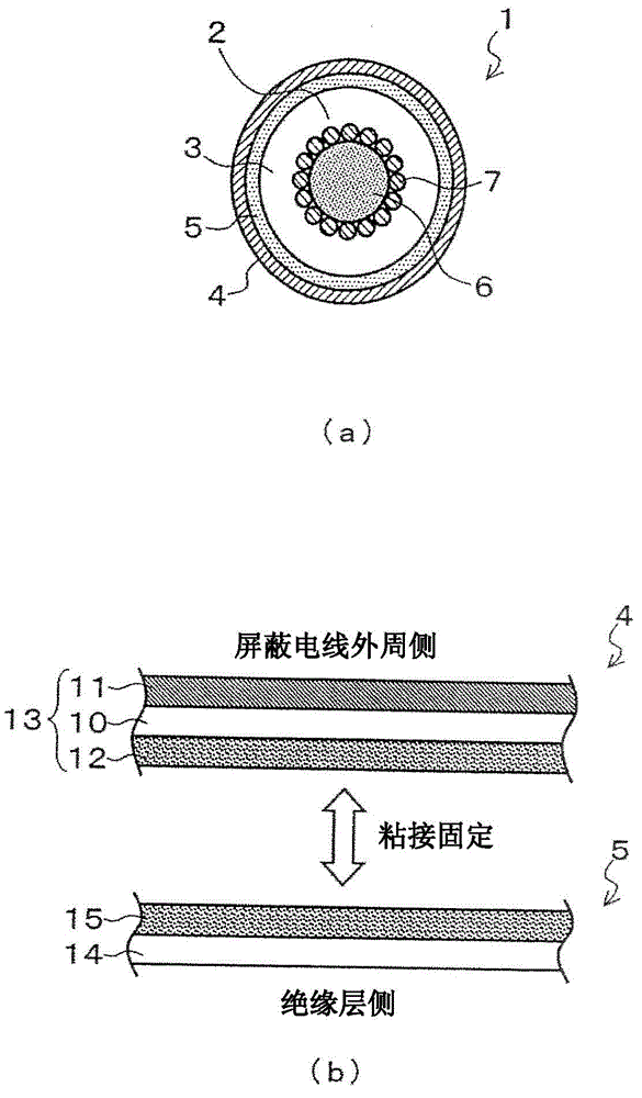
[0026] figure 1 It is a figure which shows the shielded electric wire of this embodiment, (a) is a cross-sectional view, (b) is a figure explaining bonding of a metal tape and a resin tape.

[0027] Such as figure 1 As shown in (a) and (b), the shielded electric wire 1 is configured by sequentially providing an insulating layer 3 and a shield portion (outer conductor) 4 on the outer periphery of a central conductor 2 .

[0028] In the shielded electric wire 1 of the present embodiment, the central conductor 2 is formed by spirally winding a plurality of metal wires 7 around the tensile fiber 6 .

[0029] Since the tensile fiber 6 is provided, the tensile fiber 6 can bear the tension received by the shielded electric wire 1, and the disconnection of the metal wire 7 can be suppressed. In particular, when the shielded wire 1 is sewn into a cloth-like material or the like, sin...


PUM

PropertyMeasurementUnit
thicknessaaaaaaaaaa
thicknessaaaaaaaaaa

Abstract

A shielded wire includes a center conductor, and an insulation layer and a shield that are sequentially formed on an outer periphery of the center conductor. The center conductor includes a high tensile-strength fiber and a plurality of metal strands wound around the high tensile-strength fiber.

Description

technical field [0001] The present invention relates to shielded wires, wire harnesses, circuits, cloth, clothing and sheets. Background technique [0002] In recent years, in the medical field, systems capable of constantly monitoring a patient's physical condition and actions have rapidly spread. As such a system, there is known a structure in which a circuit is incorporated in clothes or bed sheets. [0003] As a conventional circuit incorporated into clothes or sheets, a circuit using conductive fibers or metal fibers for wiring is known. [0004] In addition, there is Patent Document 1 as prior art document information related to the present application. [0005] Patent Document 1: Japanese Patent Laid-Open No. 2010-133791 [0006] However, when conductive fibers or metal fibers are used for wiring, corrosion tends to occur in an environment constantly exposed to air or moisture, and the resulting deterioration of electrical characteristics becomes a problem. In add...

Claims


Application Information

Patent Timeline
Patent Type & Authority Applications(China)
IPC IPC(8): H01B7/28H01B11/06H01B7/22H01B7/04H01B7/18
CPCH01B7/04H01B7/1825H01B3/445H01B7/2806H01B3/30A41D13/0051A47C21/048H01B7/0009H01B7/226H05B3/342
Inventor 黄得天渡部考信
Owner HITACHI METALS LTD
Learn More