
Laser LED electrode connection device

A technology of laser diodes and connecting devices, which is applied in the direction of conductive connection, electrical component connection, connection, etc., can solve the problems of complex laser structure, unsafe, short circuit or short circuit, etc. The effect of structural simplification

Inactive Publication Date: 2009-08-12
BEIJING UNIV OF TECH
View PDF3 Cites 0 Cited by
  • Summary
  • Abstract
  • Description
  • Claims
  • Application Information

AI Technical Summary

Problems solved by technology

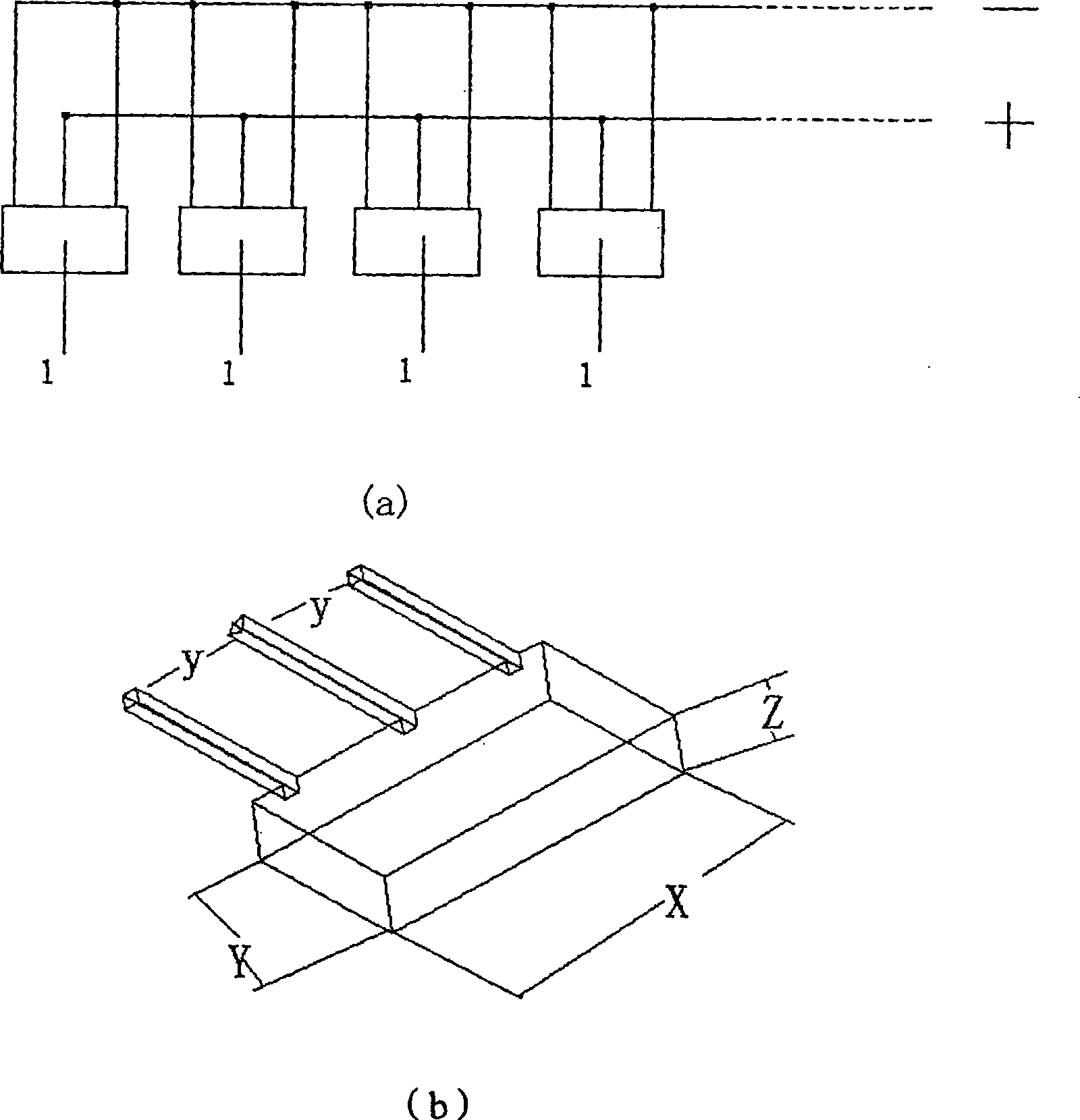
[0004] The commonly used diode electrode connection method is shown in Figure (1), which is to connect the diode electrodes through wires or adapter plugs. Due to the large operating current of the diode, the requirements for wires are very high and too many wires are connected in the laser. The laser structure becomes complex and less safe, prone to short circuits or short circuits

Method used


Image

  • Laser LED electrode connection device
  • Laser LED electrode connection device
  • Laser LED electrode connection device

Examples


Embodiment 1

[0047] Combine below Figure 1 to Figure 8 Specific embodiments of the present invention are illustrated:

[0048]The structure of the laser diode used in this embodiment is as figure 1 As shown in (b), the width X is 8mm, the length Y is 10mm, the thickness Z is 3mm, and the distance y between the positive and negative electrodes is 3mm.

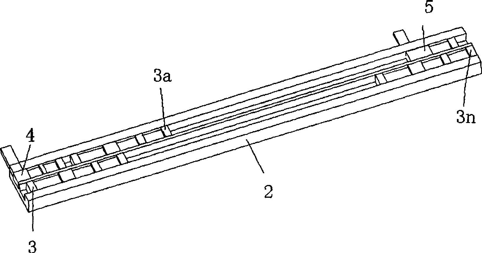
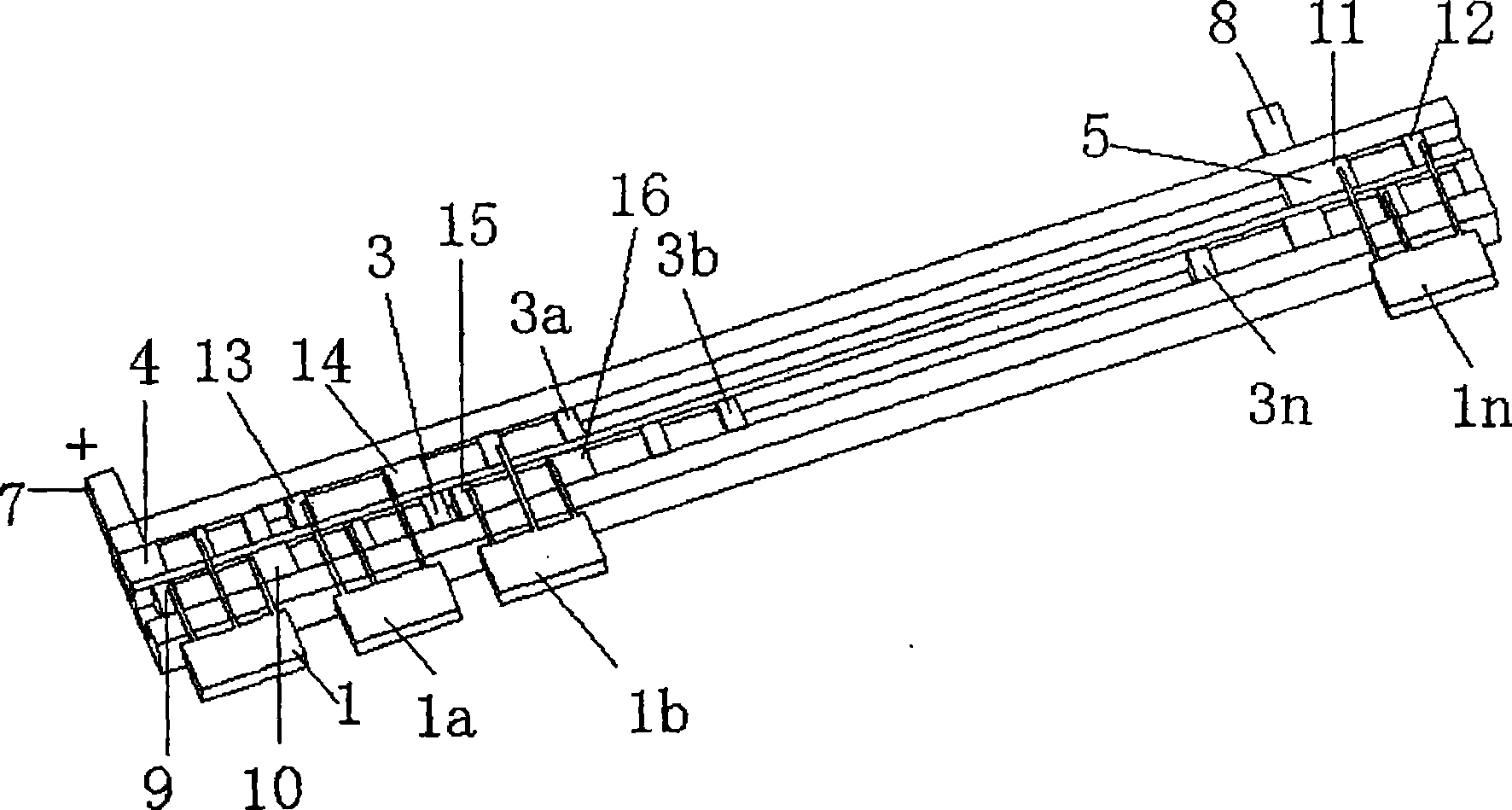
[0049] This embodiment mainly includes a bottom plate 2 made of plastic, a metal strip 3 made of metal, a positive plate 4 of a power supply, a negative plate 5 of a power supply and a plastic cover plate 6. The specific structure is:

[0050] On the plastic bottom plate 2 with a width of 15mm and a thickness of 5mm and a length of 150mm, two rows of the first groove a and the second groove b are engraved. The depth H of the two grooves is 2mm, and the width D is 3mm. The distance between the grooves is 1mm, such as Figure 2~4 shown.

[0051] Carve out two lengths at one end (at 2 mm from the end face) of a metal strip 3 with a width ...

Embodiment 2

[0070] Such as Figure 9 As shown, the structure of this embodiment is the same as that of Embodiment 1, the only difference is that the shape of the bottom plate 2 used is circular, the shape of the corresponding cover plate 6 is also circular, and the metal strips, the positive plate 4 of the power supply , The shape of the negative plate 5 of the power supply is arc-shaped.

[0071] When placed, the distance between the positive plate 4 of the power supply and the negative plate 5 of the power supply is 8mm.


PUM


Abstract

The invention is concerned with a kind of laser diode connecting equipment, belonging to whole solid-state laser technology field. This equipment takes insulated material as base plate with inside and outside grooves, and there are metal plates and positive and negative poles inside of the inside and outside grooves in certain order, and the width and thickness of metal plates and poles are same as the width and thickness of grooves. Set laser diodes on the metal plates and positive and negative poles with certain order to connect those laser diodes. This method can connect laser diodes with metal plate and has easy structure for installing and it can bear high output of current to laser diode. This method predigests the structure of whole laser to use for engineering.

Description

technical field [0001] The invention relates to a laser diode electrode connection device, which belongs to the technical field of all solid-state lasers. Background technique [0002] All solid-state lasers have the advantages of high efficiency, compactness, stability, and long life, and have important and far-reaching application prospects in industry, medical treatment, scientific research, and military affairs. With the continuous advancement of semiconductor technology, the manufacturing process of high-power diode laser arrays suitable for pumping solid-state lasers has matured, and diode-pumped solid-state lasers have developed rapidly. Rod lasers, slab lasers, sheet lasers, fiber lasers Major breakthroughs have been made in output power and beam quality, making solid-state lasers not only a leader in the information field, but also playing an important role in laser material processing, laser radar, long-distance chemical and biological remote sensing, and military ...

Claims


Application Information

Patent Timeline
Patent Type & Authority Patents(China)
IPC IPC(8): H01R9/00H01R9/28H01R11/01H01R4/28
Inventor 李强庞恺姜梦华王金国丁小艇
Owner BEIJING UNIV OF TECH
Learn More