Molten metal discharging device and method for discharging molten metal

A molten metal and molten state technology, applied in the field of molten metal ejection devices, can solve the problems of inability to insert shafts, unstable ejection volume, etc., to reduce the contact area, reduce the fluctuation of the ejection volume, and achieve high-precision control. Effect

Inactive Publication Date: 2015-11-25
MITSUBISHI ELECTRIC CORP
View PDF6 Cites 2 Cited by
  • Summary
  • Abstract
  • Description
  • Claims
  • Application Information

AI Technical Summary

Problems solved by technology

[0005] The existing molten metal ejection device cannot insert the shaft into the front end of the glass pressure cylinder
Therefore, there is a problem that, when the molten metal is extruded, the molten metal may remain at the front end of the pressure cylinder, resulting in instability of the discharge amount per time.

Method used


Image

  • Molten metal discharging device and method for discharging molten metal
  • Molten metal discharging device and method for discharging molten metal
  • Molten metal discharging device and method for discharging molten metal

Examples


Embodiment approach 1

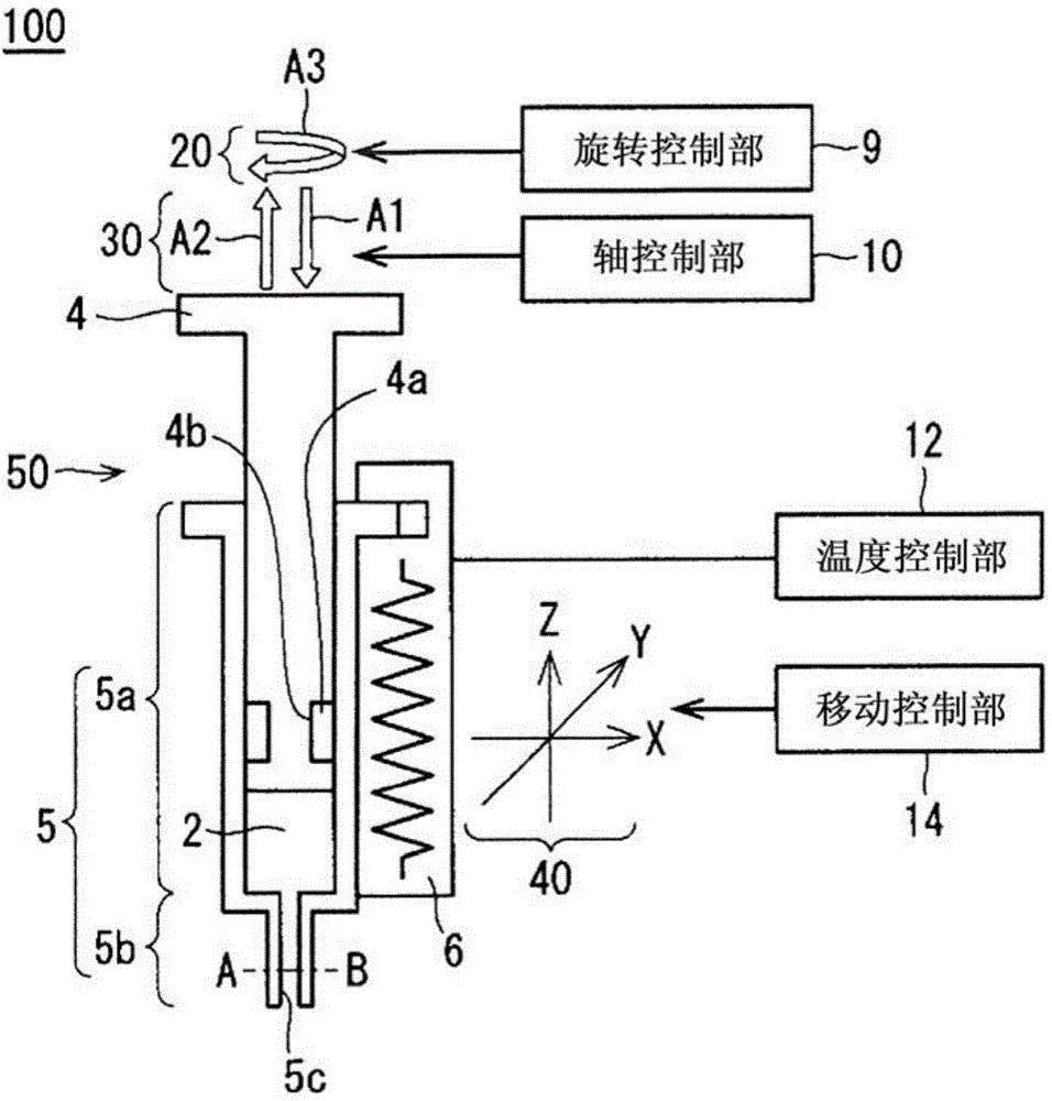
[0023] figure 1 It is a figure which shows the schematic structure of the molten metal discharge apparatus 100 in this Embodiment 1. The molten metal discharge apparatus 100 has the discharge mechanism part 50, the rotation control part 9, the shaft control part 10, the movement control part 14, and the temperature control part 12. In addition, below, in each figure, the same code|symbol represents the same or a corresponding part. The discharge mechanism unit 50 has a cylinder 5 , a shaft 4 , a cylinder heat-retaining heater 6 , a rotation mechanism 20 , an actuator 30 , and a movement mechanism 40 .

[0024] The cylindrical pressure cylinder 5 is comprised from the shaft sliding part 5a and the nozzle 5b. The inner diameter of the nozzle 5b is smaller than the inner diameter of the shaft sliding portion 5a. The nozzle 5 b sucks the molten metal 2 and accommodates it in the pressure cylinder 5 . Moreover, the nozzle 5b discharges the molten metal 2 accommodated in the pre...

Embodiment approach 2

[0056]

[0057] Figure 5 It is a figure which shows the structure of the molten metal discharge apparatus 200 in this Embodiment 2. In Embodiment 2, compared to the molten metal ejection device 100 of Embodiment 1 ( figure 1 ), and a gas pipe 7 is also provided in the shaft 4. The gas pipe 7 is connected to a gas tank (not shown), and the gas tank is filled with an inert gas such as nitrogen. The configuration is such that an inert gas can be injected into the inside of the nozzle 5 b through the gas pipe 7 . The other configurations are the same as those in Embodiment 1, and thus description thereof will be omitted. In addition, in Figure 5 in, omit figure 1 The illustration of the rotation mechanism 20 , the actuator 30 , the movement mechanism 40 , the rotation control unit 9 , the shaft control unit 10 , the movement control unit 14 and the temperature control unit 12 in FIG. from Figure 6 to Figure 8 Also omitted in the same manner.

[0058]

[0059] In the...

Embodiment approach 3

[0067]

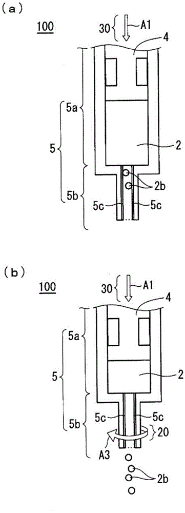
[0068] Figure 7 (a), (b) is a figure which shows the structure of the molten metal discharge apparatus 300 in this Embodiment 3. Figure 7 (a) is the state after raising the shaft 4, Figure 7 (b) is the state which lowered the shaft 4 to the front-end|tip of the nozzle 5b.

[0069] Such as Figure 7 As shown in (a), the cross section inside the nozzle 5b along the extending direction of the nozzle 5b has a narrow shape toward the tip of the opening. Specifically, for example, the shape inside the nozzle 5b is conical. In addition, the tip of the shaft 4 has a tapered shape. Such as Figure 7 As shown in (b), the tip of the shaft 4 is shaped to fit inside the nozzle 5b without a gap. In addition, the shape inside the nozzle 5b may be a triangular pyramid, a quadrangular pyramid, etc. other than a conical shape. The other configurations are the same as those in Embodiment 1, and thus description thereof will be omitted.

[0070]

[0071] When the shaft 4 i...


PUM


Abstract

A molten metal discharging device according to the present invention that discharges a molten metal and bonds components with the molten metal discharged includes: a syringe having a tube shape that houses the molten metal therein; a shaft that slides inside the syringe to press the molten metal; a heater (syringe heat insulating heater) that is provided around the syringe and heats the molten metal to maintain a molten state; and the syringe including a shaft sliding portion in which the shaft slides and a nozzle that has an inner diameter smaller than that of the shaft sliding portion and discharges the molten metal from an opening at a tip thereof, a rotation mechanism that rotates the syringe, a rotation center of the rotation being an extending direction of the nozzle, a coating that repels the molten metal being applied to an interior wall of the nozzle.

Description

technical field [0001] The present invention relates to a molten metal coating device and a molten metal spraying device, in particular to a molten metal spraying device which sprays molten metal and joins components through the sprayed metal. Background technique [0002] A molten metal ejection device is used for application of molten metal to electrodes of semiconductor elements (for example, Si chips, SiC chips, etc.) and bonding to base plates, lead frames such as copper, and the like. A typical molten metal ejection device has, for example, a pressure cylinder and a shaft made of glass. By pulling up the shaft with the tip of the pressure cylinder immersed in the molten metal, a negative pressure is created in the pressure cylinder and the molten metal is sucked in. Then, after moving the front end of the pressure cylinder to a predetermined position, the inside of the pressure cylinder is pressurized by pressing the shaft, and the molten metal is ejected (for example...

Claims


Application Information

Patent Timeline
Patent Type & Authority Applications(China)
IPC IPC(8): H01L21/67H01L21/60
CPCB23K3/0607
Inventor 仓持敬一新饲雅芳
Owner MITSUBISHI ELECTRIC CORP
Why Eureka
Try Eureka