Temperature control structure

A thermoelectric refrigerator and housing technology, applied in electrical components, circuits, semiconductor devices, etc., can solve the problems of increased thermal resistance of the heat dissipation heat path, large space, and tight device layout, so as to increase the cooling efficiency and ensure the heat dissipation effect. , The effect of reducing the thermal resistance of the case

Active Publication Date: 2015-11-25
HUAWEI TECH CO LTD
View PDF4 Cites 5 Cited by
  • Summary
  • Abstract
  • Description
  • Claims
  • Application Information

AI Technical Summary

Problems solved by technology

In the prior art, the TEC occupies a very large space inside the optical device, resulting in tight layout of the device, and cannot be integrated with the optical device, which limits the further miniaturization and packaging of the optical device; and the TEC is assembled inside the optical device, heat transfer After reaching the shell, it is emitted to the outside, resulting in an increase in the thermal resistance of the thermal circuit for heat dissipation, which in turn increases the power consumption of the TEC

Method used


Image

  • Temperature control structure
  • Temperature control structure
  • Temperature control structure

Examples


Embodiment Construction

[0029] The following will clearly and completely describe the technical solutions in the embodiments of the present invention with reference to the accompanying drawings in the embodiments of the present invention. Obviously, the described embodiments are only some, not all, embodiments of the present invention. Based on the embodiments of the present invention, all other embodiments obtained by persons of ordinary skill in the art without making creative efforts belong to the protection scope of the present invention.

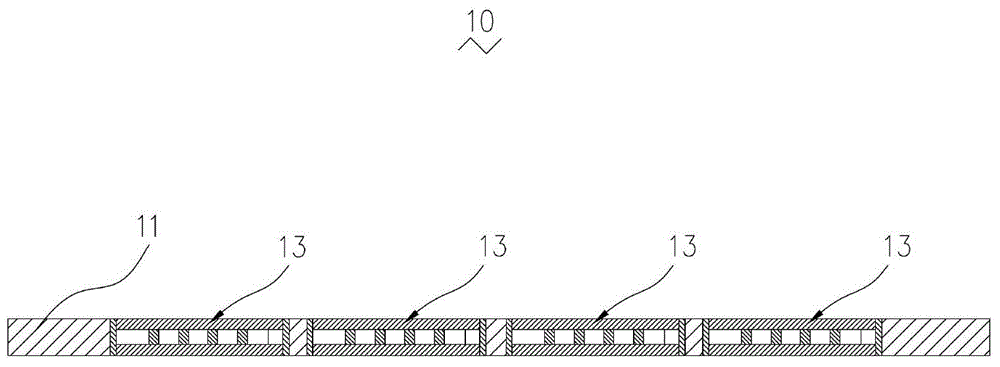
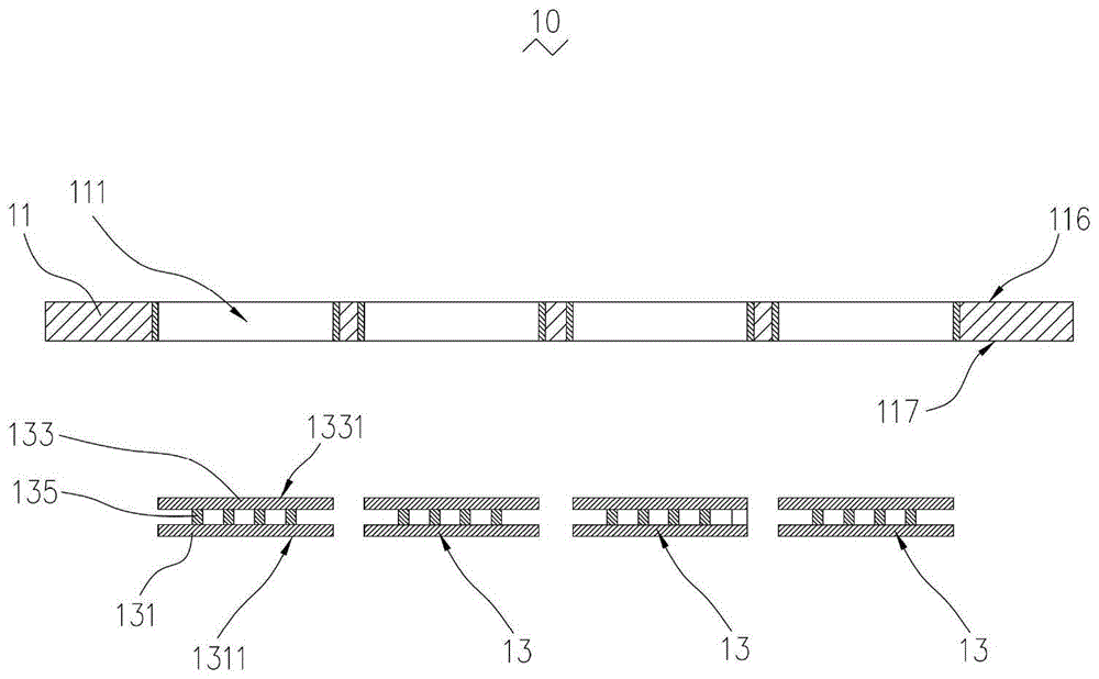
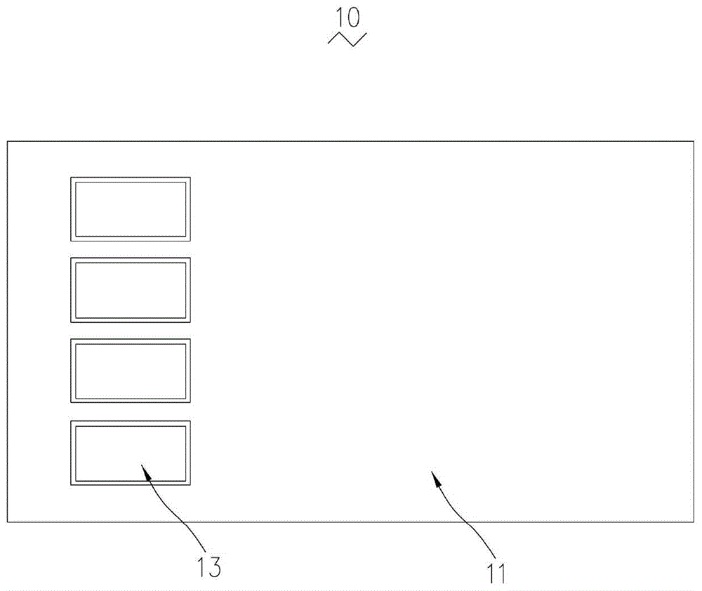
[0030] see Figure 1 to Figure 3 The first preferred embodiment of the present invention provides a temperature control structure 10, including a housing 11 and a thermoelectric cooler 13 snapped into the housing 11, and the thermoelectric cooler 13 includes cold ends 131 arranged at intervals, The hot end 133 and the semiconductor 135 connected between the cold end 131 and the hot end 133, the housing 11 is provided with an installation hole 111 for installin...


PUM


Abstract

The invention provides a temperature control structure, comprising a housing and thermoelectric refrigerators. Each thermoelectric refrigerator comprises a cold end, a hot end and semiconductors, wherein the cold end and the hot end are arranged at intervals, and the semiconductors are connected between the cold end and the hot end. The housing is provided with installing holes for embedding the thermoelectric refrigerators. According to the invention, the thermoelectric refrigerators and the housing are integrated; the dimension of a space is smaller; the hot ends and the housing can reduce thermal resistance and the power consumption of the thermoelectric refrigerators, and facilitate packaging heat dissipation.

Description

technical field [0001] The invention relates to a temperature control structure, in particular to a temperature control structure used for optical device packaging. Background technique [0002] With the development of optical communication, miniaturization and low power consumption of optical devices are required. In order to ensure the stability of the chip sending or receiving signals, it is necessary to control the temperature of the optical device chip to ensure heat dissipation. The temperature control method of the existing optical device chip is mainly realized by a thermoelectric cooler (Thermal Electric Cooler, TEC). In the prior art, the TEC occupies a very large space inside the optical device, resulting in tight layout of the device, and cannot be integrated with the optical device, which limits the further miniaturization and packaging of the optical device; and the TEC is assembled inside the optical device, heat transfer After reaching the shell, it is diss...

Claims


Application Information

Patent Timeline
Patent Type & Authority Applications(China)
IPC IPC(8): H01L33/64
Inventor 胡鹏卢伯崇刘早猛
Owner HUAWEI TECH CO LTD
Why Eureka
Try Eureka