Dual-layer patch dual-frequency disc microstrip antenna

A microstrip antenna and patch technology, which is applied in the direction of antenna, antenna grounding switch structure connection, radiation element structure, etc., can solve the problem of low bandwidth of microstrip antenna

Inactive Publication Date: 2015-11-25
SYSU CMU SHUNDE INT JOINT RES INST +1
View PDF3 Cites 14 Cited by
  • Summary
  • Abstract
  • Description
  • Claims
  • Application Information

AI Technical Summary

Problems solved by technology

However, the bandwidth of ordinary microstrip antennas is low, only 0.6%~3%, which

Method used


Image

  • Dual-layer patch dual-frequency disc microstrip antenna
  • Dual-layer patch dual-frequency disc microstrip antenna
  • Dual-layer patch dual-frequency disc microstrip antenna

Examples


Embodiment Construction

[0026] The drawings are for illustrative purposes only, and should not be construed as limitations on this patent; in order to better illustrate this embodiment, some parts in the drawings will be omitted, enlarged or reduced, and do not represent the size of the actual product;

[0027] For those skilled in the art, it is understandable that some well-known structures and descriptions thereof may be omitted in the drawings. The technical solutions of the present invention will be further described below in conjunction with the accompanying drawings and embodiments.

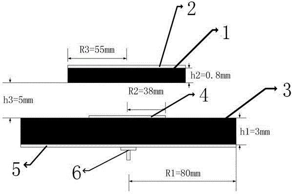
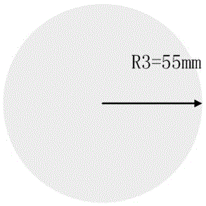
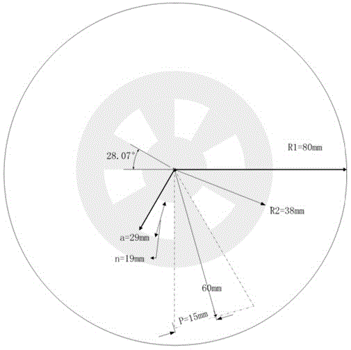
[0028] In the figure, 1-first dielectric substrate, 2-metal patch, 3-second dielectric substrate, 4-slotted circular patch, 5-metal ground plate, 6-coaxial cable.

[0029] Depend on figure 1 It can be seen that a dual-frequency disc microstrip antenna with a double-layer patch includes an upper layer part and a lower layer part, wherein the upper layer part includes a first dielectric substrate 1 and a metal pat...


PUM

PropertyMeasurementUnit
Thicknessaaaaaaaaaa
Thicknessaaaaaaaaaa

Abstract

The invention relates to a dual-layer patch dual-frequency disc microstrip antenna. The microstrip antenna discloses an upper layer part and a lower layer part, wherein the upper layer part comprises a first dielectric substrate and a metal patch located at the upper surface of the first dielectric substrate; the first dielectric substrate and the metal patch are round and have the same radius; the center of the metal patch is overlapped with the center of the first dielectric substrate; the lower layer part includes a second dielectric substrate, a grooved round patch located at the upper surface of the second dielectric substrate, as well as a metal grounding plate which is located at the lower surface of the second dielectric substrate, and a coaxial line; the second dielectric substrate is round; the center of the second dielectric substrate is overlapped with the center of the grooved round patch; a feed hole of the coaxial line is formed at the center of the second dielectric substrate; and the feeding mode of the antenna is a coaxial feed mode. According to the antenna, two resonant points can be excited, so that the relative bandwidth of the antenna can reach 19% or higher, and therefore, the working bandwidth of the antenna can be improved.

Description

technical field [0001] The invention belongs to the field of antenna design, and more specifically relates to a novel dual-frequency disc microstrip antenna with double-layer patches. Background technique [0002] The development of wireless communication puts forward new requirements for the performance of antennas (especially patch antennas). Microstrip patch antennas are light in weight, small in size, low in profile, have good directivity, and flexible feeding It has the advantages of being easy to integrate with other printed circuits, and has broad application prospects in many fields. However, the bandwidth of ordinary microstrip antennas is low, only 0.6%~3%, which becomes the main obstacle to the widespread application of microstrip antennas. Contents of the invention [0003] The purpose of the present invention is to overcome the characteristics of the narrow bandwidth of the existing microstrip antenna, and propose a dual-frequency disc microstrip antenna with...

Claims


Application Information

Patent Timeline
IPC IPC(8): H01Q1/38H01Q1/50H01Q13/08
Inventor 陈杰刘菊华龙云亮李元新
Owner SYSU CMU SHUNDE INT JOINT RES INST
Why Eureka
Try Eureka