A road piezoelectric power generation device and power generation system under the action of asynchronous vehicle load

A piezoelectric power generation and vehicle load technology, which is applied to generators/motors, piezoelectric effect/electrostrictive or magnetostrictive motors, electrical components, etc. Achieve the effect of improving the output power of electrical energy, avoiding internal consumption of electrical energy, and ensuring effective output.

Active Publication Date: 2017-08-25
CHANGAN UNIV
View PDF6 Cites 0 Cited by
  • Summary
  • Abstract
  • Description
  • Claims
  • Application Information

AI Technical Summary

Problems solved by technology

[0004] Aiming at the deficiencies in the prior art, the purpose of the present invention is to provide a road piezoelectric power generation device under the action of asynchronous vehicle load, so as to solve the problem that the existing road piezoelectric power generation device has inconsistent AC output due to uneven force
[0005] Another object of the present invention is to provide a road piezoelectric power generation system under the action of an asynchronous vehicle load to solve the problem of large internal consumption of electric energy in existing road piezoelectric power generation systems

Method used


Image

  • A road piezoelectric power generation device and power generation system under the action of asynchronous vehicle load
  • A road piezoelectric power generation device and power generation system under the action of asynchronous vehicle load
  • A road piezoelectric power generation device and power generation system under the action of asynchronous vehicle load

Examples


Embodiment 1

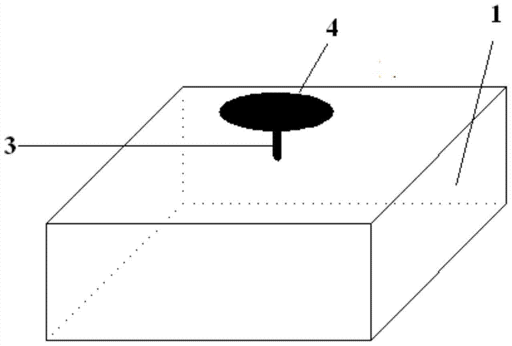
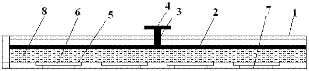
[0027] This embodiment provides a road piezoelectric power generation device under the action of an asynchronous vehicle load, such as Figure 1 to Figure 3 As shown, the box body 1 is included: a piston 2 is arranged in the box body 1, a piston rod 3 protruding from the upper surface of the box body 1 is installed on the piston 2, and a piston rod 3 extending from the outer surface of the box body 1 is installed with a force plate 4;

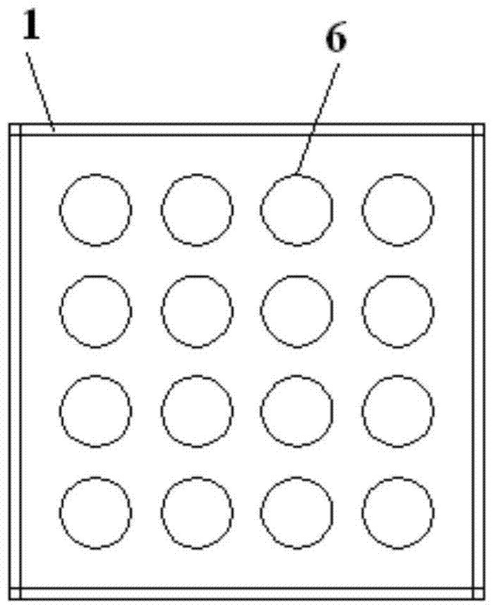
[0028] The interior of the lower surface of the box body 1 is processed with a plurality of fixed slots 5, each fixed slot 5 is equipped with a piezoelectric ceramic sheet 6, and the plurality of piezoelectric ceramic sheets 6 are connected in parallel, each piezoelectric ceramic A deformation groove 7 is provided on the box body 1 below the sheet 6;

[0029] The casing 1 between the piston 2 and the piezoelectric ceramic sheet 6 is filled with hydraulic oil 8 .

[0030] The box body 1 is a rigid box body, the inner surface of which is welded...

Embodiment 2

[0034] This embodiment provides a road piezoelectric power generation system under the action of asynchronous vehicle load, such as Figure 1 to Figure 4 As shown, a plurality of road piezoelectric generators 11 are arranged symmetrically on the roadway wheel marks 10 of the asphalt concrete layer 9 of the road, and the road piezoelectric generators 11 are the road piezoelectric generators described in Embodiment 1. ;

[0035] The road piezoelectric generators 11 symmetrically arranged on the same cross section of the road are first connected in parallel, and then connected to the rectifier circuit 12. The output terminal of the rectifier circuit 12 is equipped with a diode 13 that only allows current to be output from the rectifier circuit 12. A generating group 14 is formed on the surface;

[0036] Each generating set 14 is then connected in parallel, and then connected to a load 16 through a filter circuit 15 .

[0037] The same generating set 14 can output consistent ele...


PUM


Abstract

The invention provides a road piezoelectric power generation device and a power generation system under asynchronous vehicle load action. Road piezoelectric power generation devices arranged symmetrically on the same cross section of a road are connected in parallel first, and then connected with a rectifier circuit, the output end of the rectifier circuit is equipped with a diode allowing current to be output only from the rectifier circuit, and a generator set is formed on the same cross section of the road. All the generator sets are connected in parallel, and then connected with a load through a filter circuit. The action forces consistent in magnitude and direction on the surfaces of piezoelectric ceramic power generation chips ensure that all the piezoelectric ceramic power generation chips output alternating current in step. By adopting the system, reverse flow of electric energy is blocked, the problem that the electric energy of the road piezoelectric power generation devices arranged at intervals along the driving direction is consumed internally under direct and inverse piezoelectric effects is avoided, and effective output of all electric energy is ensured.

Description

technical field [0001] The invention belongs to the field of road engineering and relates to piezoelectric power generation, in particular to a road piezoelectric power generation device and power generation system under the action of a non-synchronous vehicle load. Background technique [0002] During the service life of the asphalt pavement, it will bear millions of times of vehicle loads, and considerable mechanical vibration energy is accumulated inside the pavement structure, part of which is dissipated into the air in the form of heat energy, and the other part will eventually cause the pavement structure to If this part of energy can be harvested and converted into electrical energy, it will bring considerable economic and social benefits. A wide range of research has been carried out in this field at home and abroad. Most of the research results are based on the positive piezoelectric effect of piezoelectric materials. Piezoelectric transducers are developed and desi...

Claims


Application Information

Patent Timeline
Patent Type & Authority Patents(China)
IPC IPC(8): H02N2/18
Inventor 王朝辉韩晓霞李彦伟高志伟李岩军封栋杰石鑫陈森问鹏辉
Owner CHANGAN UNIV
Why Eureka
Try Eureka