Current coordination control method of electrically-excited synchronous motor

A technology of current coordination and synchronous motors, which is applied in the direction of motor generator control, electronic commutation motor control, and control systems. Air gap flux linkage oriented vector control is complex and other issues, to achieve the effect of speeding up torque response, overcoming saturation, and reducing requirements

Inactive Publication Date: 2015-11-25
TSINGHUA UNIV
View PDF4 Cites 13 Cited by
  • Summary
  • Abstract
  • Description
  • Claims
  • Application Information

AI Technical Summary

Problems solved by technology

In the existing research on electric excitation synchronous motors, electric excitation synchronous motors with damping windings are more widely used, and damping windings can speed up the torque current response speed, but the air gap flux linkage oriented vector control is very complicated in the dynamic process, and with the At the end of the dynamic process, the current of the damping winding gradually decays, which cannot offset the armature reaction effect of the stator current, and it is difficult to output multiple overload torques solely by the function of the damping winding
However, there are few related researches on electric excitation synchronous motors without damping windings, which mainly focus on the improvement of traditional basic control strategies, and almost no corresponding researches solve the two problems of output torque capability and torque response speed at the same time.

Method used


Image

  • Current coordination control method of electrically-excited synchronous motor
  • Current coordination control method of electrically-excited synchronous motor

Examples


Embodiment Construction

[0016] The embodiment of the present invention provides a current coordinated control method of an electrically excited synchronous motor, which overcomes the saturation of the magnetic circuit in the torque current direction under heavy load by canceling the magnetomotive force of the stator and rotor air gap in the d-axis direction, and improves the motor performance. output torque capability, while speeding up the torque response speed.

[0017] Embodiments of the present invention are described in detail below in conjunction with the accompanying drawings: the specific implementation is as follows:

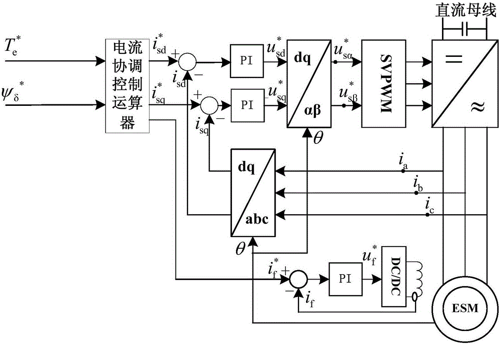
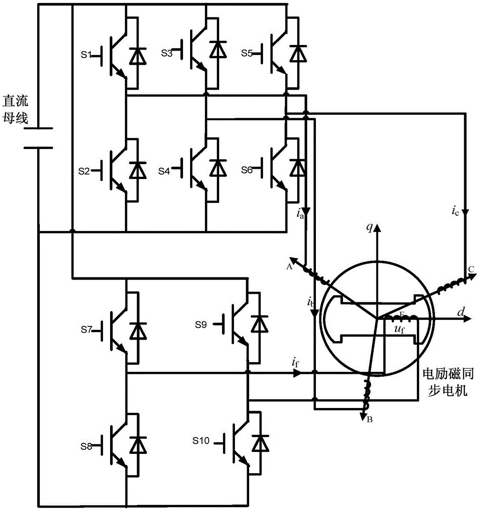
[0018] Such as figure 1 Shown is a block diagram of the current coordinated control method of the present invention, figure 2 It is a schematic diagram of the main circuit structure of an electrically excited synchronous motor.

[0019] The specific implementation is as follows:

[0020] according to figure 1 The block diagram of the current coordinated control system is ...


PUM


Abstract

The invention discloses a current coordination control method of an electrically-excited synchronous motor, which belongs to the field of motor control. In the method, an exciting current, a torque current and a compensation current in a electrically-excited synchronous motor system are defined. Under coordination control of the currents, a stator q shaft current serves as the exciting current and is used for generating an air gap magnetic field so as to keep a stator air gap flux linkage constant; a rotor current serves as the torque current and acts with the air gap magnetic field to generate electromagnetic torque; and a stator d shaft current serves as the compensation current, and a certain proportion relation is maintained between the stator d shaft current and the rotor current, so that a stator air gap magnetomotive force and a rotor air gap magnetomotive force in the direction of a d shaft are cancelled. The realization mode of the method is simple, the magnetic circuit saturation problem under a heavy duty is overcome, the linear relation between the electromagnetic torque and the torque current can be basically maintained if multiple overload torque is output, and the torque output capability is substantially improved; in addition, the torque response speed is greatly improved, and the problem of an insufficient inverter output voltage under the heavy duty condition is solved.

Description

technical field [0001] The invention belongs to the field of motor control, in particular to a current coordination control method of an electric excitation synchronous motor. Background technique [0002] In some important applications, such as elevator drives, heavy machine tools, mining machinery, and ship electric propulsion, in order to improve control accuracy and operational reliability, low-speed high-torque direct drive methods are often used. At the same time, in electric vehicle drives, short-term The intermittent overload operation mode expects the motor to output a high multiple of overload torque. In occasions where the dynamic response of speed and position is extremely high, such as the motor-driven operating mechanism of a high-voltage circuit breaker, the effective action time is tens of milliseconds, and the motor is required not only to output multiple overload torques, but also to have a torque response speed of milliseconds class. Therefore, improving...

Claims


Application Information

Patent Timeline
Patent Type & Authority Applications(China)
IPC IPC(8): H02P21/12
Inventor 柴建云孙旭东熊志师喻
Owner TSINGHUA UNIV
Why Eureka
Try Eureka