
Voice signal generator capable of adjusting pulse waveforms

A pulse waveform and sound signal technology, which is applied in the field of sound signal generators with adjustable pulse waveforms, can solve the problems of single function, inability to adjust pulse waveforms, and inability to realize separate adjustments, etc., and achieve the effect of expanding the scope of application

Inactive Publication Date: 2015-11-25
周致
View PDF6 Cites 3 Cited by
  • Summary
  • Abstract
  • Description
  • Claims
  • Application Information

AI Technical Summary

Problems solved by technology

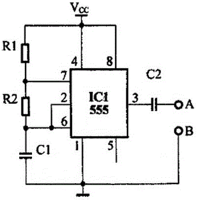
The defect of this sound signal generator is that it can only output a fixed pulse square wave signal, and the pulse waveform cannot be adjusted. When testing the sound signal, it cannot test a variety of sound signals.
Therefore, the NE555 pulse signal generator can only test multi-frequency sound signals, but cannot test the amplitude and duty cycle of the signal, which shows that its function is single
[0004] Aiming at the problem of the single function of the NE555 pulse signal generator, those skilled in the art can easily think of adding an adjustable signal duty cycle circuit on the basis of the NE555, expecting to realize the functions of adjustable duty cycle and frequency, but so far, When the NE555 module combined with duty cycle and frequency adjustable circuit is working, the frequency will change while adjusting the duty cycle, or the duty cycle will change while adjusting the frequency, that is, the two must be simultaneously Adjustment, mutual influence, unable to achieve separately adjustable functions

Method used


Image

  • Voice signal generator capable of adjusting pulse waveforms
  • Voice signal generator capable of adjusting pulse waveforms

Examples


Embodiment Construction

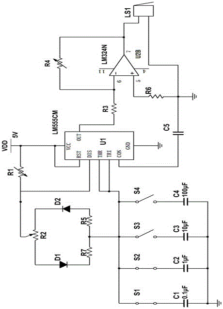
[0012] see figure 1 , The present invention has a 555 timer U1, its model is LM555CM. The VCC pin of the 555 timer U1 is connected to the power supply VDD and one end of the adjustable resistor R1 at the same time, and the power supply VDD uses a 5V power supply. The other end of the adjustable resistor R1 is connected to the discharge end DIS of the 555 timer U1 and the sliding end of the potentiometer R2 at the same time. The other end is connected to the cathode of the diode D2, the anode of the diode D2 is connected to one end of the resistor R5, the other end of the resistor R5 is connected to the other end of the resistor R7 and the FM parallel circuit, and the FM parallel circuit is simultaneously connected to the 555 timer U1 The threshold terminal THR and the trigger terminal TRI , form a Schmitt trigger, and ground the ground terminal of the FM parallel circuit.

[0013] The output terminal OUT of the 555 timer U1 is connected to one end of the resistor R3, the ot...


PUM


Abstract

This invention discloses a voice signal generator capable of adjusting pulse waveforms. A VCC pin of a 555 timer is simultaneously connected with a power supply and one end of an adjustable resistor R1; the other end of the adjustable resistor R1 is connected with a discharge end of the 555 timer and a sliding end of a potentiometer R2; one end of a fixed end of the potentiometer R2 is connected with a positive pole of a diode D1; a negative pole of the diode D1 is connected with one end of a resistor R7; the other end of the fixed end of the potentiometer R2 is connected with a negative pole of a diode D2; the positive pole of the diode D2 is connected with one end of a resistor R5; the other end of the resistor R5 is simultaneously connected with the other end of the resistor R7 and a frequency-modulation parallel circuit; the frequency-modulation parallel circuit is simultaneously connected with a threshold end and a trigger end of the 555 timer; the output end of the 555 timer is connected with one end of a resistor R3; the other end of the resistor R3 is connected with an inverting input end of an operational amplifier; an adjustable resistor R4 has a series connection between the output end and the inverting input end of the operational amplifier. Thus, the frequency, the duty ratio and the amplitude of the output voltage can be adjusted separately, and only one of the frequency, the duty ratio and the amplitude is changed without affecting the others.

Description

technical field [0001] The invention relates to a signal generator using a 555 timer, in particular to a sound signal generator with an adjustable output pulse waveform, which is used to test the sound quality performance of speakers or earphones, and to overhaul and measure the sound of speakers and earphones. As a multi-functional sound signal generator, the teaching and research laboratory is also suitable for sound signal testing and speaker listening testing in factory production workshops. Background technique [0002] The sound signal generator is a triode oscillating circuit. The signal generator circuit using 555 timer sound is simple, easy to vibrate and has high efficiency. The circuit structure of the commonly used sound signal generator is as follows figure 2 As shown, this sound signal generator is connected to a capacitor C2 at the output end of the 555 timer, and the output signal is coupled through the capacitor C2; the capacitor C1 is charged through the r...

Claims


Application Information

Patent Timeline
IPC IPC(8): H03K3/017H03K3/02
Inventor 周致
Owner 周致
Learn More