Phase-locked loop system

A phase-locked loop and phase technology, applied in the field of phase-locked loop systems, can solve the problems of the deterioration of the noise contribution of the charge pump, the inability of the clock skew to meet the requirements of the index, and the deterioration of the skew index of the anti-skew phase-locked loop. skewed effect

Active Publication Date: 2015-11-25
SEMICON MFG INT (SHANGHAI) CORP
View PDF10 Cites 7 Cited by
  • Summary
  • Abstract
  • Description
  • Claims
  • Application Information

AI Technical Summary

Problems solved by technology

[0006] In view of the shortcomings of the prior art described above, the purpose of the present invention is to provide a phase-locked loop system for solving the problem that the traditional anti-skew phase-locked loop in the prior art can only bring limited gain, and the limited The clock skew of the gain elimination cannot meet the requirements of the index, which causes the problem of deterioration of the skew index of the anti-skew PLL, or the traditional anti-skew PLL reduces the clock skew by reducing the current of the charge pump , which in turn causes the problem that the noise contribution of the charge pump deteriorates

Method used


Image

  • Phase-locked loop system
  • Phase-locked loop system
  • Phase-locked loop system

Examples


Embodiment Construction

[0056] Embodiments of the present invention are described below through specific examples, and those skilled in the art can easily understand other advantages and effects of the present invention from the content disclosed in this specification. The present invention can also be implemented or applied through other different specific implementation modes, and various modifications or changes can be made to the details in this specification based on different viewpoints and applications without departing from the spirit of the present invention.

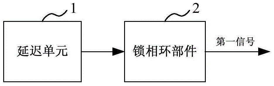
[0057] see figure 2 , the phase-locked loop system of the embodiment of the present invention at least includes: a delay unit 1, which is used to delay the reference clock signal and the feedback clock signal; a phase-locked loop component 2, which is connected to the delay unit 1, and is used to The clock signal is fed back, and the first signal locked to the frequency and phase of the reference clock signal is output. It should be...


PUM


Abstract

The invention provides a phase-locked loop system, wherein the phase-locked loop system at least comprises the components of a delay unit which is used for delaying a reference clock signal and a feedback clock signal; and a phase-locked loop component which is connected with the delay unit and is used for outputting a first signal that is locked on the frequency and the phase of the reference clock signal based on the delayed reference clock signal and the feedback clock signal. According to the phase-locked loop system, through overlapping the delay unit into the phase-locked loop component, delaying the reference clock signal and the feedback clock signal, and performing reversal digital compensation on a phase difference between the reference clock signal and the feedback clock signal, inclination of the reference clock signal and the feedback clock signal is eliminated, and the performance of the phase-locked loop component does not reduce. Through adjusting the delay precision of the reference clock signal and the feedback clock signal, fine adjustment for the phase difference under locking of the original locked-phase loop is realized, so that under a precondition that the performance of the phase-locked loop component is ensured, 10ps-20ps magnitude phase locking can be realized.

Description

technical field [0001] The invention relates to a phase-locked loop, in particular to a phase-locked loop system with a digital compensation function capable of eliminating clock skew. Background technique [0002] The clock in the SoC system (System on Chip, system on chip) usually needs to generate a series of clocks that are not skewed with the clock source for the subsequent system. However, skew (skew) will inevitably occur during the transmission of the clock. At this time, the SoC system usually requires that the skew be limited to a smaller index, so as to ensure that the sampling modules in the subsequent systems have sufficient design margins. As the system clock frequency increases gradually, the requirement for this skew index becomes higher and higher. [0003] The traditional anti-skew phase-locked loop (deskewPLL, deskewPhaseLockingLoop), like the clock generator phase-locked loop, can generate an output clock phase-locked reference clock. However, unlike th...

Claims


Application Information

Patent Timeline
IPC IPC(8): H03L7/099H03L7/085
Inventor 陈先敏
Owner SEMICON MFG INT (SHANGHAI) CORP
Why Eureka
Try Eureka