Pulse compression method of CHIRP signals, and wireless signal transceiver thereof

A pulse compression and wireless signal technology, applied in the direction of sinusoidal signal conversion, power amplifier, digital transmission system, etc., can solve the problems of high cost, long CHIRP signal calculation cycle, complex system, etc., to reduce time cost and low storage space cost , the effect of reducing complexity

Active Publication Date: 2015-11-25
燕力欣
View PDF6 Cites 4 Cited by
  • Summary
  • Abstract
  • Description
  • Claims
  • Application Information

AI Technical Summary

Problems solved by technology

[0006] The present invention proposes a pulse compression method for CHIRP signals to solve the technical problems of long calculation period when performing pulse compression on CHIRP signals in the prior art, need to synchronize CHIRP signals, complex system and high cost

Method used


Image

  • Pulse compression method of CHIRP signals, and wireless signal transceiver thereof
  • Pulse compression method of CHIRP signals, and wireless signal transceiver thereof
  • Pulse compression method of CHIRP signals, and wireless signal transceiver thereof

Examples


Embodiment

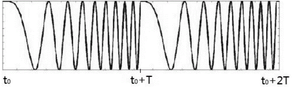
[0034] In the CSS (CHIRPSPREADSPECTRUM) communication system, the transmitter sends a series of CHIRP signals into the air, which can be expressed as: C 1 , C 2 , C 3 ,...C k ......C K , 1≤k≤K, where K is the number of CHIRP signal cycles required to complete a communication. Let the period of the CHIRP signal be T and the bandwidth be B.

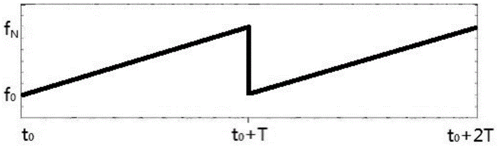
[0035] figure 1Shown is a typical periodic UPCHIRP signal. The UPCHIRP signal has the following characteristics: the amplitude is constant; the frequency changes linearly with time, such as figure 2 shown, and taking T as the period, define t N = t 0 +T; signal bandwidth B=f N -f 0 . Obviously, when a transceiver receives a specific CHIRP signal, its instantaneous frequency component f n (0≤n≤N) will appear in chronological order, ie f n should only be at t n (0≤n≤N) appears at all times.

[0036] The pulse compression process of the CHIRP signal in the present invention is to perform different delay operations for different...


PUM


Abstract

A pulse compression method for CHIRP signal and a wireless transceiver thereof; pulse compression processing of a cycle C k has the following steps: analytically obtaining all instantaneous frequency components of instantaneous signals and then isolating out a corresponding amplitude; using storage spaces M n to store the amplitude and phase of each of the instantaneous frequency components; setting T n as a length of time from t n to an end time of the corresponding cycle; calculating T n according to formula T n =T-t n ; using another set of storage spaces M T to rearrange amplitudes of the different instantaneous frequency components; storing the amplitude of each of the instantaneous frequency components in a set of T n value corresponding storage spaces of M T space; and accumulating overlapping amplitudes of instantaneous frequency components into another space in the storage spaces M T .

Description

technical field [0001] The invention relates to a pulse compression method of a CHIRP signal (chirp frequency modulation signal), and a wireless signal transceiver based on the pulse compression method. Background technique [0002] As a linear frequency modulation signal, the CHIRP signal is expressed by a mathematical formula as: [0003] f(t)=f 0 +st0<t<T [0004] Among them, f 0 It is the starting frequency of the CHIRP signal, and s represents the slope of its frequency change. When s>0, it means that the frequency of the CHIRP signal is continuously increasing within the signal period, which is called UPCHIRP (ascending chirp signal); when s<0 Indicates that the frequency of the CHIRP signal is continuously decreasing within the signal period, which is called DOWNCHIRP (descending chirp signal). It can be seen from the above formula that the instantaneous frequency at any moment corresponds to the moment, which is also the inherent law of the CHIRP sign...

Claims


Application Information

Patent Timeline
Patent Type & Authority Applications(China)
IPC IPC(8): H04B1/7163
CPCH04B1/69H03M5/22H04B2001/6912H04L27/103H03F3/24H04B1/40H04B2001/0416H04B2001/0408
Inventor 燕力欣
Owner 燕力欣
Why Eureka
Try Eureka